What Does
Cell Resistance Tester Mean?
A cell resistance tester is a device used to measure the opposition to current flow (i.e., electrical resistance) in electrical cells. Various resistance testers and methods are available to check the condition of a circuit or piece of equipment. Resistance is measured in ohms, which is symbolized by the Greek letter omega (Ω).
The resistance testing of electrical equipment covers a wide range of techniques depending upon the nature of the cell/circuit tested and the type of test required. For example, while contact resistance testing at the poles may yield a result in the range of tens of micro-ohms, insulation resistance testing in a circuit breaker is on the order of 1000 MΩ. These two forms are both classified as resistance testing, but the test equipment and techniques for each one differs in accordance to the objectives and the items to be tested.
Many components such as heating elements and resistors have a fixed resistance value printed on the component's nameplate or listed in their reference manuals. Sometimes a tolerance range is indicated, in which case the measured resistance value is required to be within the specified range. Any significant change in a fixed-resistance value could indicate a problem.
Cell resistance testers are used to determine the condition of a component or a circuit. The higher the resistance in a circuit, the lower the current flow. An abnormally high resistance can be caused by damaged conductors that either burned out or experienced corrosion.
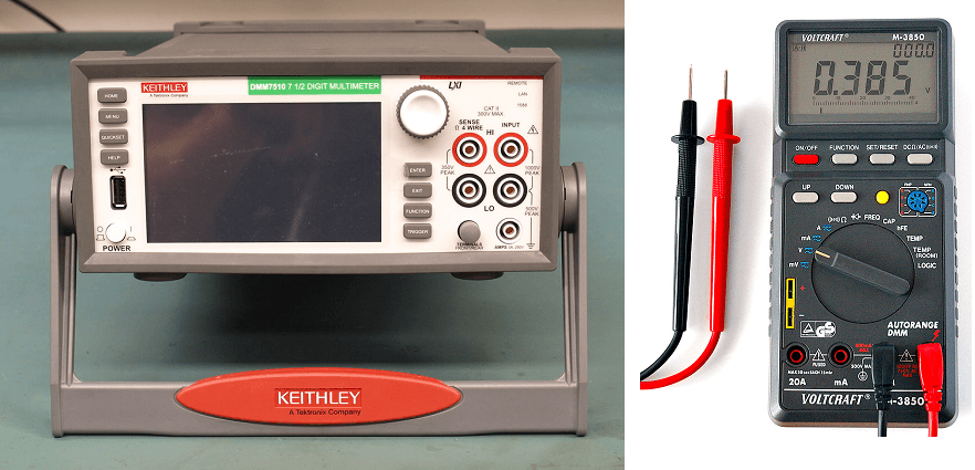
Figure 1. Two digital multimeters that can be used for cell resistance testing. (Source: "Keithley DMM7510 7.5 Digit Bench Multimeter" by eevblog is marked with CC0 1.0 and "File:Digital Multimeter Aka.jpg" by André Karwath aka Aka is licensed under CC BY-SA 2.5)
All conductors typically give off some heat, and overheating is often associated with resistance. This can be minimized if the resistance is closely monitored. Corrosion can increase the resistance in an electrical circuit. Excessive resistance in the circuit can also cause voltage problems. For these reasons it is important that resistance be measured and minimized.
Corrosionpedia Explains Cell Resistance Tester
Usually the resistances of electronic and electrical components start out low and increase over time due to factors like wear-and-tear and corrosion. However, loads such as motors tend to decrease in resistance over time due to insulation breakdown and moisture.
Some factors that may affect the test result include foreign substances (e.g., dirt or oil), finger contact with the metal ends of the test leads, or parallel circuit paths that occur when fingers come into contact with the circuit and become a parallel resistance path that lowers the total circuit resistance.
How to Perform a Cell Resistance Test with a Multimeter
The general steps to perform a cell resistance test with a typical multimeter are:
- Turn off power to the circuit.
- If a circuit has a capacitor, the capacitor should be discharged before taking any resistance reading.
- Turn the test meter's mode selection dial to resistance, or ohms. The readout should display zero ohms before the test leads are connected to any components.
- Insert the black test lead into the COM jack.
- Insert the red lead into the VΩ jack.
- Connect the probe's test leads across the component being tested, ensuring that the contact between the test leads and circuit is solid.
- Read the measurement on the tester's display.
- When finished with the test, remove the leads in the reverse order: red first, then black.
- Turn off the test meter to prevent draining the battery.
For very low-resistance measurements, use the relative mode, also referred to as zero or delta (Δ) mode because it automatically subtracts the resistance of the test leads.
When working on a circuit board, it may become necessary to lift up one of the leads of the resistor from the board in order to obtain an accurate measurement. The resistance displayed by a digital multimeter is the total resistance through all possible paths between the test lead probes.