Pipelines are often located in common utility rights of way with the pipeline taking advantage of corridors reserved for high voltage AC (HVAC) overhead electrical transmission lines. The efficient use of public lands for common utilities offers many advantages when it comes to planning and routing of both overhead and underground services. This is particularly true for highly industrialized or heavily developed urban and near urban areas.
However, one consequence of placing utilities in a common right of way is that energy can be transferred to the neighboring pipeline by three possible mechanisms: conductive coupling (during fault conditions), capacitive coupling and inductive coupling. The resulting induced AC voltage (stray current) can present problems for pipeline operators.
Our first goal here is to discuss this phenomenon and show how it can affect the integrity of the affected pipelines. Later on we will briefly explain mitigation methods for this interference problem.
Factors Affecting Interference between AC Power Lines and Pipelines
Interference between pipelines and high voltage transmission lines depend on several factors that can be summarized as follows:
- Length of parallelism between the pipeline and the high voltage transmission line. The greater the length of parallelism the greater the induced voltage over the pipelines.
- Transmission line voltage and current. The greater the voltage the greater the induced voltage on the pipelines.
- Lateral distance between pipelines and transmission lines. As the distance increases the induced voltage decreases.
- Pipeline coating type, its dielectric strength and coating efficiency.
Methods of Interference
As mentioned above, electrical energy can be transferred from an overhead power line to a nearby pipeline by three methods. These are:
- Conductive coupling (during fault conditions)
- Capacitive coupling
- Inductive coupling
In the following sections we will explain how each method of interference occurs to a neighboring pipeline.
Conductive (Resistive) Coupling
Conductive coupling occurs when there is a phase to ground fault or phase to phase to ground fault. When this fault occurs a substantial amount of current flows from the power line and enters the earth. This fault current must return back to its source using any paths available to it. These paths will include the power line shield wire, the earth and the metallic structures in the earth including the neighboring pipelines.
Resistive coupling is most pronounced during a short circuit condition on a power system. In this case a large amount of current flows to the earth through the tower, pole or substation grounding. This current flow raises the potential of the earth near the structure, often to thousands of volts with respect to remote earth. This high voltage stresses the coating of neighboring pipelines and could cause arcing that damages the coating or the structure itself. Also, this high voltage difference could represent an electric shock hazard if the structure is touched.
Resistive coupling effects are dependent on several factors, including:
- Short circuit current magnitude
- Power line overhead ground wire type and length back to the source
- Size of foundation and grounding system of poles, substations or towers through which the fault current is flowing
- Soil electrical resistivity with respect to depth
- Separation distance between the affected metallic structure and the power system
Electrostatic (Capacitive) Coupling
Any two conductors separated by a dielectric material can be considered a capacitor. In our case here, capacitive coupling occurs due to the presence of an above ground pipeline laid on an insulated skid underneath an overhead transmission line. This case is common when a string of newly constructed pipes are laid waiting to be welded. In this case we have two capacitors in series. The first one is between the overhead power conductor and the pipeline with the air acting as the dielectric material. The other capacitor is between the pipeline itself and the earth because earth is also a conductive plate (although non-metallic). (Related reading: Stray Current Corrosion and Preventive Measures.) This is shown in the figure below.
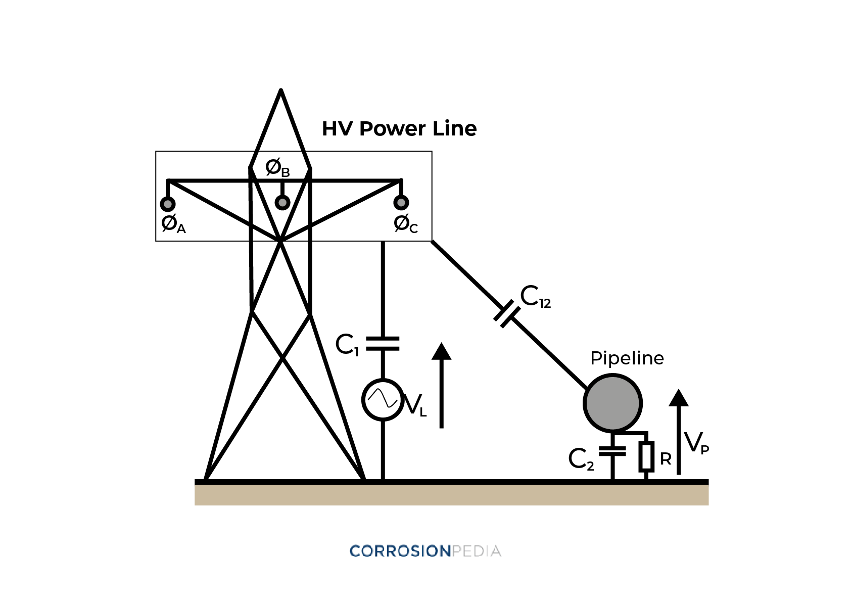
Figure 1. Capacitive coupling between a high voltage power line and a pipeline.
The amount of voltage picked up by the structure from overhead power lines is dependent on several factors, such as:
- The structure's size
- Its proximity to power lines
- The voltage level of the power conductor and its geometrical arrangement
Depending on power line voltages, a single pipeline jointthat is very well insulated from ground could pick up very large voltages (on the order of thousands of volts). Luckily, because the capacitance values between the pipelines and the power line voltages are very small (on the order of picofarads), the capacitive reactance between them is very large (in the giga-ohm range), so very little energy is transferred to the pipeline with this mechanism.
Although the energy transferred by electrostatic coupling is so small that not enough current is produced that could create an electric shock hazard, it can result in nuisance voltages that have a feeling similar to a shock from static electricity. This could create a secondary safety hazard if anyone overreacted to the sensation of this voltage while working on a pipeline project.
Inductive Coupling
Whenever there is a relative motion between an electrical conductor and a magnetic field, a voltage is induced onto this conductor. The relative motion could be due to physical movement of the conductor itself through a stationary magnetic field (as in the case of a generator), or could be due to the movement of a magnetic field around a stationary conductor (as in the case of a transformer).
In our case here we have a stationary electric conductor, which is the buried pipeline, and we have a rotating magnetic field coming from the neighboring power line. The presence of the rotating magnetic field induces a voltage onto the pipeline. The magnitude of the induced voltage is dependent on several factors. The most important are:
- The separation distance between the pipeline and the power line
- The length of exposure (parallelism) between the pipeline and the power line
- Power line current magnitude
- Coating resistance of the buried pipeline
- Grounding of the pipeline
- Soil resistivity as a function of depth
It should be noted that considerable power is transferred to pipelines due to inductive coupling. The power transmitted can result in tens or hundreds of amperes to be flowing in the nearby pipeline during peak power operating conditions. It can even reach thousands of amperes in fault conditions. Potential peaks occur at locations where there are abrupt changes in parameters, as in areas where the pipelines and the power lines deviate away or cross each other. (Related reading: Corrosion and Electrical Interference in Buried Metallic Structures.)
AC Corrosion
Link for alternating current corrosion:
The effect of AC current in causing corrosion of buried pipelines has been a great controversy since 1916. It was originally thought that the AC current corrosion effect was negligible compared to the DC current effect. However, in the 1990s it was realized that several cathodically protected (CP) pipeline failures were due to AC current leaking from buried pipelines. This raised the alarm that AC current could be a contributing factor to pipeline corrosion and could pose a threat to the pipelines' integrity.
The mechanism with which steady state AC current causes corrosion to pipelines is still not completely understood. However, it was realized that there is a relation between AC current density and the corrosion rate of the pipeline. Further studies have shown that there is an AC current density threshold at which corrosion occurs. This can be shown as follows:
iac < 20 A/m2 ——————————————-> No corrosion
20 A/m2 <iac < 100 A/m2 —————————–> Corrosion unpredictable
iac > 100 A/m2 ——————————————-> Corrosion expected
A more recent study presented in NACE standard practice SP21424 -2018 has showed a different criteria to determine if AC corrosion is expected. In this study the AC current density was related to the DC current density coming from cathodic protection systems, as follows:
iac < 30 A/m2 if DC current density exceeds 1A/m2
iac < 100 A/m2 if DC current density is less than 1A/m2
AC current density (iac) at a circular holiday is a function of the induced AC voltage on the pipeline (Vac), soil resistivity ⍴ (Ω.cm) and holiday diameter d (cm). AC current density can be calculated as follows:
iac = 8Vac / (ρπd)
Where:
iac ———> AC current density (A/m2)
Vac ———> Induced voltage on pipeline (V)
⍴ ———–> Soil resistivity (Ω.m)
d ———–> Holiday diameter (m)
From the equation above we can conclude that the AC current density increases as the holiday diameter decreases. Thus we can say that AC corrosion is most likely to occur at pinholes rather than large defects. In fact it was realized that corrosion rates increase with decreasing holiday sizes. This trend will continue to be true until the holiday size is about 1 cm2. If a holiday size is smaller than 1 cm2 then AC corrosion will not be a problem.
In one case study, pictures of AC corrosion showed an anomaly on a holiday in a cathodically protected pipeline. The site of the anomaly showed a polarized potential of about -1170 mVCSE and a pH greater than 12. When the anomaly was cleaned from corrosion products, a corrosion pit was discovered although the pipeline appeared to be well-protected according to measured pipe to soil potentials. Based on the holiday diameter (0.01 m), soil resistivity (16 Ω.m) and the AC induced pipeline voltage (50 V), the AC current density was calculated to be 800 A/m2 and so AC corrosion was concluded.
How to Mitigate the Effect of AC Interference on Pipelines
The effect of AC interference can be divided into two parts. The first part is mainly related to capacitive and resistive coupling where a large amount of current can be transferred to the pipeline resulting in an unintended rise in the potential of the pipeline. If the test post terminals are touched (as when potential measurements are being taken during a CP survey), the potential rise could result in electrocution and death. (Related reading: The Benefits of Timely and Effective Reporting When Conducting Pipeline Close Interval Surveys.) This is called a touch potential.
Another safety consideration occurs when fault current flows from the power system to the neighboring structure, especially in fault conditions. This current flow can create a voltage gradient in earth that can affect a person standing on earth without touching the energized structure. This is called a step potential. Step and touch potentials are presented in the following diagram:
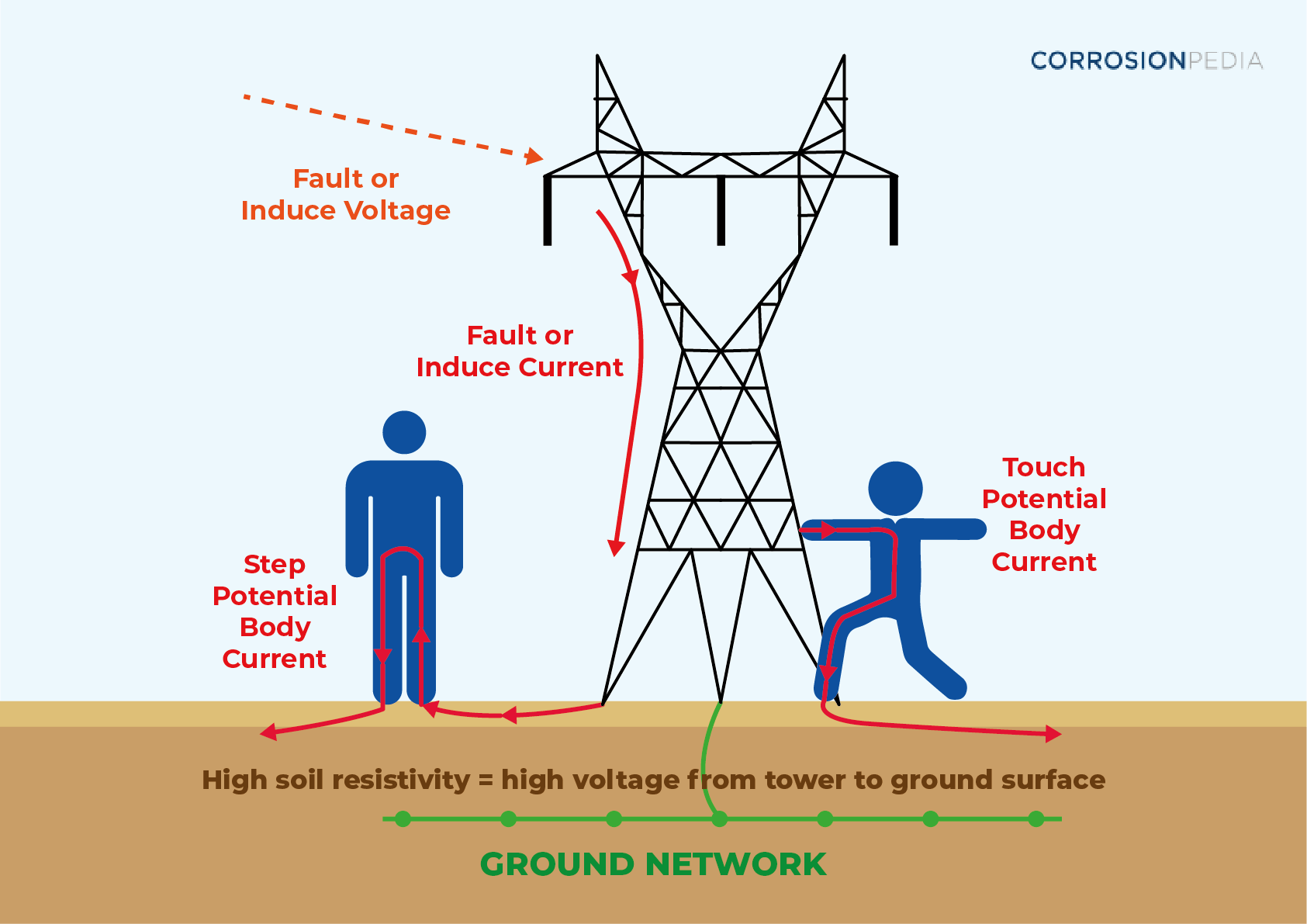
Figure 2. Step and touch potential.
The second problem that arises due to AC interference is the occurrence of AC corrosion problems, as we explained above. Because in this article we are emphasizing the discussion of AC corrosion, we will try to explain the mitigation methods used to minimize the occurrence of AC corrosion to buried pipelines. Mitigation methods for step and touch potential are beyond the scope of this article.
Mitigation of AC Corrosion
AC corrosion is mainly mitigated through grounding of the pipeline that is under the influence of the overhead power line. This will lower the pipeline coating's resistance and will lower the voltages induced over the pipeline.
Grounding can be done through different materials. For example, we can use packaged sacrificial anodes or we can use sacrificial anode ribbons installed in a special backfill. (Related reading: Cathodic Protection and Anode Backfills.) In addition to this we can use conventional grounding materials such as copper grounding rods or cables.
However, using materials that are cathodic to the pipelines like copper grounding rods can reduce the effectiveness of the CP system if they are directly connected to the pipeline. Therefore, if we are willing to use conventional grounding materials, they should be DC decoupled from the pipeline using a polarization cell or a solid state replacement to polarization cells that are most commonly used these days.
Polarization cells have various uses but in our case we use it to DC decouple the more cathodic grounding material from the pipeline while at the same time allowing the flow of AC voltages induced onto the pipelines to the ground. This will allow the connection between conventional grounding materials and pipelines without affecting the CP system.
Other mitigation methods are presented in SP21424-2018-SG, “Alternating Current Corrosion on Cathodically Protected Pipelines: Risk Assessment, Mitigation, and Monitoring” as follows:
- Control of cathodic protection condition. As shown above, AC current density that could cause AC corrosion is related to the DC current density from CP systems. Therefore, maintaining a uniform level of CP across the pipeline is necessary to mitigate AC corrosion. The CP power source locations should be optimized such that the CP level is neither excessive nor inadequate, as both cases can lead to initiation of AC corrosion if AC current densities are within the threshold levels that could cause AC corrosion.
- Control of DC interference currents. Anodic and cathodic DC interference must be controlled and mitigated as mentioned in NACE SP0169, "Control of External Corrosion on Underground or Submerged Metallic Piping Systems." AC corrosion is expected in areas suffering from inadequate CP levels as in anodic interference areas or from excessive CP levels at cathodic interference areas.
Conclusion
Placing underground pipelines far from power lines is considered the best solution to prevent the occurrence of AC interference. However, the lack of free space and the desire to efficiently use right-of-ways has made this ideal solution nearly impossible. Today, pipeline owners find themselves obliged to place their pipelines close to power lines. This has elevated the problem of AC interference with its hazardous effects on personnel safety and the pipeline's integrity.
It is therefore extremely important that pipeline designers take into account the presence of AC interference and design a mitigation method to be implemented before pipelines are buried in the ground and put into service. Pipeline owners and operators must also monitor the presence of AC interference and take rapid action if measurements revealed that AC corrosion could be a problem.