Cathodic protection is among the most widespread and accessible techniques for corrosion mitigation. Owing to the sizeable losses and inconvenience that corrosion can cause for industry, accurate and reliable measurements in the monitoring of cathodic protection are essential so that the possibility of erroneous readings does not impact asset owners unexpectedly.
This expert guide to achieving accurate cathodic protection measurements offers a detailed explanation and divides principally into two halves. The first half covers the use of digital multimeters (DMMs, but specifically the ohmmeter function) by offering guidelines for their use and how to obtain accurate readings for evaluating the effectiveness of dielectric insulating fittings. The second half of this article offers a thorough grounding and insight into the correct use and care of reference electrodes for cathodic protection measurements and concludes with suggestions on how to address some of the limitations and possible errors corrosion professionals experience in recording such measurements. The topics explained here include environmental factors that affect measurements, electrode accuracy, care, conditioning, maintenance and the use of different electrodes. Some expert tips and answers to common questions are also included here.
Digital Multimeters (Ohmmeters)
The modern portable digital multimeter (DMM) is an indispensable tool with many functions and features. Typically, a DMM is used to measure AC and DC voltages and currents. In addition to these features, they also include an Ω (ohm) function to measure the electrical resistance between two points.
Under the right conditions, the ohmmeter can accurately measure from 1 ohm to as much as 60 megohm (60 million ohms). The key phrase here is “under the right conditions.” The DMM operator needs to understand how the meter functions and the conditions that can yield errors in measurement.
All ohmmeters will apply a regulated current (typically one milliamp) through the test leads across the circuit being measured. The applied current will result in a voltage drop across the component being tested. The meter utilizes an algorithm calculation that uses Ohm’s Law (R=E/I) to calculate and display the resistance in ohms, kilohms, or megohms.
Guidelines For Ohmmeter (DMM) Use
Using an ohmmeter is straightforward. Yet, it is important to follow some basic guidelines to ensure accurate measurements and safety. Following are guidelines for using an ohmmeter:
- Safety First: Always ensure that the circuit or device you intend to test is disconnected from any power source, which includes unplugging the power cords or switching off circuit breakers. This prevents the risk of electric shock and damage to the ohmmeter. Once the device is not energized, testing can proceed.
- Clean Contacts: Ensure that the test leads (wires with probes) and items to be tested are clean and free from any debris or oxidation. Dirty contacts can affect the accuracy of the resistance measurement.
- Disconnect Components: If testing a specific component within an electrical circuit, make sure the component is disconnected from the electrical circuit. This prevents parallel paths from affecting the measurement.
- No Voltage: Don't measure resistance in a circuit where voltage is present. Voltage can interfere with the ohmmeter's reading and potentially damage the device.
- Switch the DMM Dial to the Ohm (Ω) Function: Ensure the correct meter function has been selected.
- Test the Meter: Short the two test leads together to ensure the meter and leads function correctly. The DMM reading should be stable and repeatable. It is common for test lead cables to have between 0.3 and 1.0 ohms. Therefore, when measuring low-resistance devices, such as a fuse or a length of wire, remember that the resistance of the meter test leads will be added to the measuring circuit.
- Hold the DMM Probes Properly: Hold the test lead probes with their insulated handles when measuring resistance. Avoid touching the metal parts of the test lead probes, as this can introduce additional resistance to the measurement and be very misleading when measuring high-resistance devices.
- Good Contact: Press the probes firmly against the test locations to ensure the metal probes make good electrical contact with the points being measured.
Testing Dielectric Fittings with an Ohmmeter
In the cathodic protection (CP) industry, technicians often use an ohmmeter to determine the condition of a dielectric insulating flange, union, or similar fitting. While it may seem straightforward to use the ohmmeter, it will likely provide unreliable results. This is why the following should be considered:
When testing an installed dielectric fitting, i.e., connected to a pipeline on both sides of the dielectric fitting, even if the CP system is in the OFF condition, there will likely be a voltage differential across the two sides of the dielectric fitting. This will violate the above guidelines #3 & #4. This voltage will be applied to the internal calibration circuitry of the DMM and will result in an inaccurate resistance measurement. Therefore, this measured value is only “interesting information” due to its inaccurate value. If the test lead polarity is reversed and the test repeated, an entirely different resistance value would appear. The good news is that if the DMM reads some value of resistance, it would mean that the fitting is NOT shorted, as a shorted dielectric fitting would read close to zero ohms.
In the case of a dielectric isolating flange, an electrically shorted or resistive fitting can be caused by several different problems. Obviously, if the gasket has failed or “bridged” internally, the quality of electrical isolation will be compromised. In the case of dielectric insulating flange kits, if the isolation between the threaded stud and the flange is compromised, the flange may be shorted or not affect the isolation.
To provide electrical isolation of a flanged pipe fitting, the flange gasket must be made of an electrically isolating material, and the threaded studs of the fitting must be electrically isolated from at least one of the flange faces. There are two configurations of flange isolation kits:
- Single Washer and Sleeve, below. With this configuration, the individual studs will be electrically isolated from one of the two flanges.
-
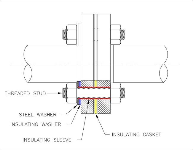 Figure A
- Double Washer and Sleeve, below: All the threaded studs are electrically isolated from both flanges in this configuration. This is by far the most popular configuration.
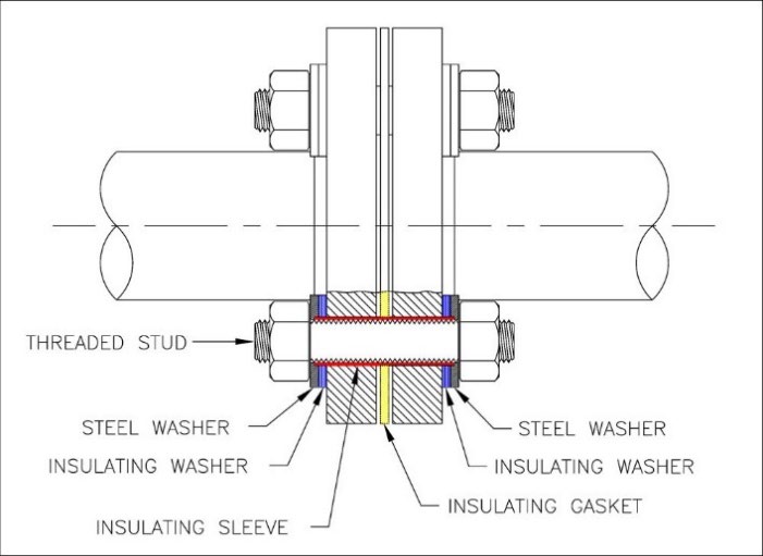 Figure B
An ohmmeter can properly test electrical isolation between the flange and the threaded studs.
When testing FIGURE A, assuming the gasket provides electrical isolation, the resistance between the stud and flange 1 will indicate some resistance. However, this again violates guidelines #3 & #4, which is not a good idea. Testing between the stud and flange 2 will indicate zero resistance.
When testing FIGURE B, assuming the gasket provides good electrical isolation, the resistance between the stud and either flange should be high.
If it is possible to test a dielectric insulating fitting before installation, you should do so with the
dielectric fitting (isolating union, assembled flange, monolithic isolating joint, or similar) on a non-conductive surface, such as wood. Because there will be no voltage differential between the two sides of the fitting, using an ohmmeter to test the effectiveness of the dielectric fitting is a proper test.
Reference Electrodes for Cathodic Protection
In almost all cases, the reference electrode is used as a zero-reference point concerning the structure under test. The voltage differential between the structure under test and the reference electrode is commonly called a “structure-to-electrolyte potential” and the electrolyte is usually soil or water.
A typical example of measuring a structure-to-electrolyte potential would be where a reference electrode is placed in the soil or water (the electrolyte surrounding the structure) and connected through a test wire to one terminal of a voltmeter. The other terminal of the voltmeter is connected directly to the structure. This creates a bimetallic or galvanic “cell” between the reference electrode and the structure through the electrolyte. In this electrical circuit, the structure is one electrode, and the reference electrode is the other electrode. Hence, the reference electrode is often called a “half cell.”
Because the reference electrode is considered a stable (zero) reference voltage, any changes measured in the structure-to-electrolyte potential must occur on the structure (voltage or IR drop in the soil is not considered and is a subject for another time).
The characteristic potential of a reference electrode is determined by the metallic element that the reference is built from. There are many types and configurations of reference electrodes, but for most CP applications, four types are commonly used. These include:
- Copper-copper sulfate (CuCuSO4) used in soil and freshwater applications.
- Silver-silver chloride (AgAgCl) used in seawater, high saline water and mud.
- Zinc (Zn) used in soil, seawater, high saline water and mud.
- Iron or steel, often referred to as a “coupon,” fabricated from the same metal of the protected structure.
This can be used to emulate a “native or natural potential” coupon when it is not connected to the structure.
Or it can be used as a “protected potential” coupon when electrically connected to the cathodically protected structure.
Coupons are often used as a “zero voltage” reference electrode in high temperature or severe environments that might destroy a conventional reference electrode.
What Voltage Level Equals Full Protection?
It is important, if not critical, to know the type of reference electrode used during structure testing. Different reference electrodes have different relative potentials that represent full protection of a structure. In the information below, you can see this relationship.
The voltage values for each referenced electrode type to achieve full protection of steel is:
CuCuSO4 = Negative 0.850 Volts (-0.850 V)
AgAgCl = Negative 0.800 Volts (-0.800 V)
Zn = Positive 0.250 Volts (+0.250 V)
External influences will affect the accuracy of the reference electrode. These include:
- Temperature
- Light
- Electrolyte concentration
- Electrolyte contamination or electrode polarization
Temperature Effect
Temperature variations can affect the voltage reading taken per the example below:
Potential at 90°F = -0.865 V
Potential at 40°F = -0.840 V
Portable reference electrodes can be maintained at a relatively constant temperature. However, stationary reference electrodes are subject to the temperature of the environment. Be mindful of this when measuring or attempting to check the calibration or accuracy of a stationary or in situ reference electrode.
Light Effect
Copper salts and silver salts are photo (light) sensitive. As a result, exposure to light will change their relative zero point. Experiments have demonstrated that in the case of a CuCuSO4 reference electrode, a difference of as much as -0.0520 Volts (-52mV) can occur on a reference electrode that transitions from total darkness to bright sunlight (clear summer solstice). This means that the measured potential would be 52 mV lower in the sunlight than in the dark. Reference electrode manufacturers recognize this characteristic, and as a result, they have eliminated the clear reference electrode tubes or the tubes with a clear or view window. If you are using a reference electrode with a clear or view window, it is advised that you cover the window with dark tape.
Electrolyte Concentration Effect
Electrolyte concentration should be considered when selecting a reference electrode for field measurements. Both CuCuSO4 and AgAgCl electrodes can be affected by electrolyte concentration.
CuCuSO4 electrodes can become contaminated in high chloride environments. This contamination will affect their accuracy. See below for additional information.
AgAgCl electrodes require relatively high concentrations of chlorides to function properly.
Contamination Effects
Contamination of the electrode’s internal electrolyte can affect the characteristic potential of the electrode because the electrode is now in a conflicting chemical environment. Once contaminated, the potential of the electrode can be significantly affected. In practice, this will be a problem if the electrode is subjected to high concentrations of contaminants. CuCuSO4 electrodes are particularly sensitive to chloride contamination.
When using a CuCuSO4 electrode in brackish or seawater, the chlorides migrating back through the porous electrode plug will eventually result in an inaccurate or compromised electrode. When contaminated, the electrode’s CuCuSO4 solution turns to a cloudy or milky blue.
If no other solutions are available, you can use a CuCuSO4 electrode in seawater or brackish water/mud. In this instance, it is important that the electrode’s liquid level be filled to a maximum to minimize air within the electrode. This will reduce the number of chlorides migrating back through the porous plug and contaminating the CuCuSO4 solution. Also, you should only use the electrode in shallow (<25 ft.) water and minimize the time the electrode is immersed. If the CuSO4 solution becomes contaminated, disassemble the electrode and flush and clean the components with distilled water. Once clean, renew the CuSO4 solution by mixing CuSO4 crystals and distilled water. The porous ceramic plug should be discarded and replaced with a new one, as the ceramic will be contaminated.
Checking Accuracy of a CuCuSO4 Reference Electrode
As discussed, many factors can affect the accuracy of a reference electrode, so you should monitor your electrodes for accuracy. Electrode manufacturers do this with the use of a laboratory-grade Calomel reference electrode or a standard hydrogen electrode. Both are quite expensive, and Calomel electrodes are not legal in all states because they contain mercury.
Portable CuCuSO4 reference electrodes are the most popular choice in the cathodic protection (CP) industry. Many companies use a brand-new and properly serviced CuCuSO4 reference electrode as their “gold standard” by which all other electrodes will be compared. This standard electrode will never be used for fieldwork, which minimizes the possibility of contamination or other scenarios that may compromise the standard portable electrode.
How to Know If the Reference Electrode Is Accurate
The author has conducted a series of comparative tests to evaluate the practicality of this method by using three new reference electrodes from three different manufacturers, making a total of nine electrodes under test. The reference electrodes were properly serviced before testing. The test consisted of taking two reference electrodes and contacting the moistened ceramic plug together while measuring the millivolt (mV) differential between the two electrodes. In a perfect world, the differential measurement would be zero volts. However, it was found that the overall minimum to maximum differential between different manufacturers was 19 mV. And the differential voltage among individual manufacturers was:
- Manufacturer “A,” 12 mV
- Manufacturer “B,” 5 mV
- Manufacturer “C,” 3 mV
In a typical CP field survey, if the “measured” potential was within 10 mV from the “actual” potential, this differential would represent less than a 2% error in most cases. This would have a minimal effect of skewing the overall survey results or the ability to evaluate the CP system's performance properly. However, this differential becomes more important during a close interval survey (CIS) when having multiple reference electrodes close to a zero potential differential is important.
Care & Maintenance of Reference Electrodes
To help maintain a portable CuCuSO4 reference electrode:
- Keep the plastic cap on the ceramic, porous tip when the electrode is not in use.
- Be sure the CuSO4 solution remains bright blue (not milky) and has an adequate liquid level. A milky appearance of the CuSO4 solution indicates that the solution is contaminated.
- Always carry new CuSO4 crystals and distilled water to clean and recharge your portable reference electrode.The porosity and relative durability of ceramic tips vary between manufacturers. If you are fortunate, you will get a reference electrode that does not leak the CuSO4 solution even with the cap off. Either way, keep your reference away from sensitive metallic components, i.e., meters, precision tools, etc., as the CuSO4 solution is very corrosive.
Reconditioning a CuCuSO4 reference electrode:
- Clean all internal electrode components with distilled water.
- Remove oxidation or contamination from the copper rod with either a Scotch Bright pad or "garnet sandpaper.” Never use aluminum oxide sandpaper or any type of steel wool or wire brush, as this will contaminate the copper rod.
- Check, clean or replace O-ring seals to prevent leaks.
- Recharge the electrode with new CuSO4 crystals to approximately 50% before adding water.
- Use only distilled water or approved premixed CuSO4 solution.
Post-survey maintenance on a portable AgAgCl reference electrode would include rinsing the electrode with fresh, potable water to flush out any residual salts or chlorides. When clean, allow the electrode to air-dry and store it in a clean plastic bag.
Alternative Types of CuCuSO4 Reference Electrodes
Alternative reference electrode technologies are available that eliminate the need for much of the maintenance described above. The new technology provides components that are contained in a sealed unit that incorporates a non-porous, ionically conducting end plug. This electrode is calibrated at the factory and shipped with a Certificate of Calibration. For more information about these options, refer to MP Magazine article, “Submersible Reference Electrodes Revisited.”
Maintenance and Unserviceability of Copper-Copper Sulfate Reference Electrodes
Portable copper-copper reference electrodes require maintenance to preserve the integrity of readings taken when using the electrode.
Maintenance should be done on a periodic basis depending on how often the electrode is used or the conditions in which it is used. A good rule of thumb for rejuvenating an electrode is when the copper sulfate liquid inside the electrode becomes “milky” as the color should be a very bright blue.
Maintaining or Rejuvenating Portable Copper-Copper Reference Electrodes
- Open the reference electrode by unscrewing the plastic end cap where the copper rod is mounted.
- Properly dispose of the liquid copper sulfate.
Note: This liquid is hazardous. Proper safety measures should be employed including the use of safety glasses and disposable gloves.
- Clean the internal copper rod with a non-metallic abrasive, such as sandpaper or a scouring pad. This will remove any patina or impurities from the rod.
Note: NEVER use metallic abrasives to clean the rod, such as an emery cloth, as it will contaminate the copper rod.
- Add new, pure copper sulfate crystals to the interior of the reference electrode by removing the end cap of the electrode. Fill the electrode cavity to approximately one-third to half full.
- Add clean, distilled water to the interior of the electrode filling the electrode to almost full.
Note: NEVER use tap water for this purpose.
- Replace the plastic end cap by threading it back onto the electrode body.
- Ensure the ceramic tip of the electrode is clean and in good condition. A cracked ceramic tip should be replaced with a new tip to avoid excessive electrolyte leakage.
Why do copper sulfate reference electrodes become unserviceable?
The most frequent problem with many permanent, soil-type cathodic protection reference electrodes (CPREs) is that they simply dry out over time. Once the CPRE is dehydrated, the resistance-to-earth will increase, and the CPRE will eventually be affected by meter loading. Even if the CPRE is installed in permanent moisture, they still have a finite life.
For a copper sulfate CPRE to function, an adequate amount of copper sulfate solution must permeate the porous end plug and migrate into the soil or water. Eventually, the volume of copper sulfate will be depleted, and once that occurs, the CPRE will become unreliable even in a damp environment. How long it takes for the copper sulfate to be depleted is a question that has a complex answer. The physical size of the CPRE, the volume of copper sulfate reserves, the soil composition and relative moisture all affect the service life of the CPRE.
Accurate Measurement of Pipe-to-Soil Potentials in Cathodic Protection
Measuring Pipe-to-Soil Potentials
Most cathodic protection technicians will measure pipe-to-soil potentials (PSP) using a digital
multimeter (DMM) and a cathodic protection reference electrode (CPRE).
The following scenario may be familiar: Your task is to conduct a PSP survey on a cathodically protected pipeline. You have history with this system and expect good levels of protection over the entire pipeline. You set up your DMM and portable CPRE to measure a PSP at a known test point and find that the reading is 50% lower than expected. As you have done many times before, you add water to the soil around the CPRE (which you probably should have done in the first place) and find that the PSP is now reading as expected.
Question: Why was the potential reading higher after adding water? Voltage is voltage. Certainly, the water does not create voltage. So, what is going on?
All DMMs will impose a load on all voltage circuits measured. Most professional-grade DMMs have an input resistance of 10 MΩ. (million ohms). When the DMM is connected to a voltage source, it imposes a load of 10 MΩ. This may seem high, but when used to measure very sensitive (high resistance) circuits, the meter’s load on the circuit can result in a significant error, as illustrated in the above example. This condition is referred to as "meter loading". In the example above, adding water to the soil around the CPRE reduces its contact resistance to earth and voltage drops across the CPRE-to-soil interface. This allows the CPRE to produce adequate current to properly operate the DMM resulting in a more accurate PSP measurement.
Question: What is meter loading?
Once connected to the circuit under test (CPRE-to-structure), the current required to operate the DMM changes the conditions in the circuit compared to what it was before the meter was connected. If the CPRE has a high contact resistance to the soil, the ability of this compromised or weak galvanic cell cannot provide adequate energy to operate the DMM properly. As illustrated in the above example, the meter is imposing a load on the CPRE circuit that can result in a significant (lower than actual) error.
An analogy is when the batteries in a flashlight become weak, and the light output reduces. That is
because the light bulb is not getting the required voltage to operate it properly. Consider the light bulb as the DMM, and the weak batteries as the galvanic cell created between the CPRE and the structure in this example.
The ideal DMM would have infinite input resistance, creating zero-meter loading and no reduction of the measured voltage.
Meter loading will affect the ability to obtain an accurate reading from any CPRE, even under the best conditions. Fortunately, for most instances, the effect from meter loading is minimal, and the resultant error is considered acceptable.
In the case of stationary CPREs and/or coupons, adding water is not typically possible or practical.
Therefore, is the low PSP reading you see truly low, or is it low due to meter loading? Without
specialized metering equipment, there is no way for the technician to know if the reading is accurate or compromised.
One area where meter loading is common is when measuring PSP readings from a stationary CPRE. When a lower-than-expected reading is indicated, the question is: Now what? Once a stationary CPRE is tested and confirmed to be compromised, the technician has five choices:
1. Accept the lower reading, understanding that it may be inaccurate or compromised due to meter loading.
2. Purchase a specialty DMM with a higher input resistance to obtain a more accurate reading.
3. Retire the CPRE and consider it unserviceable.
4. Install a new stationary CPRE to replace the compromised CPRE.
5. Purchase a specialty instrument to eliminate the effects of meter loading.
Note: this content has been edited and reproduced with permission from the Farwest Corrosion Blog.