Cathodic protection is a corrosion control technique used to mitigate the corrosion of underground or submerged metallic structures. There are two types of cathodic protection systems: impressed current and galvanic anodes, which are selected according to the properties and requirements of the protected structure. (For a quick introduction, watch VIDEO: Cathodic Protection in 2 Minutes Flat, or read the article The Basics of Cathodic Protection.)
In order to ensure corrosion control of underground or submerged metallic structures, adequate cathodic protection is a must. So, periodic function testing and troubleshooting of applied cathodic protection systems is required to ensure correct operation of the system.
Here we'll talk about cathodic protection system function testing and troubleshooting.
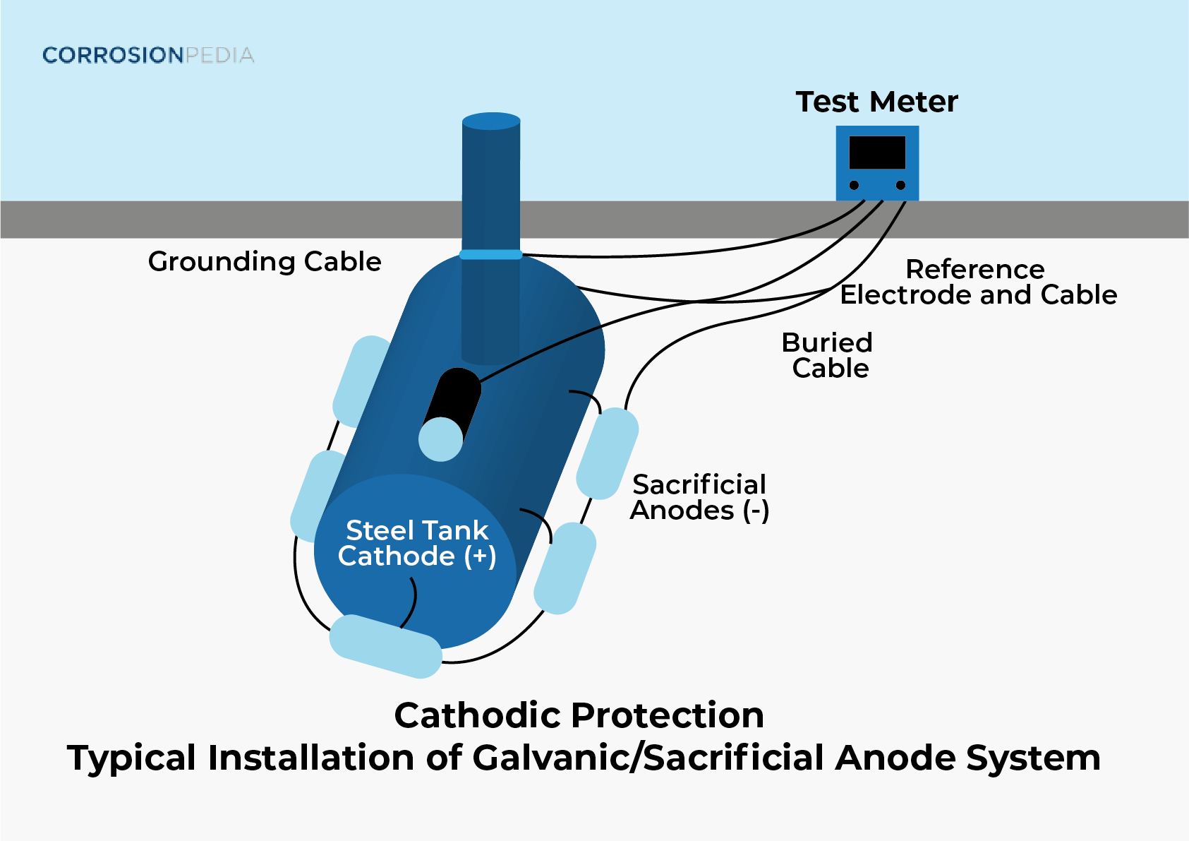
Figure 1. Typical galvanic sacrificial anode system.
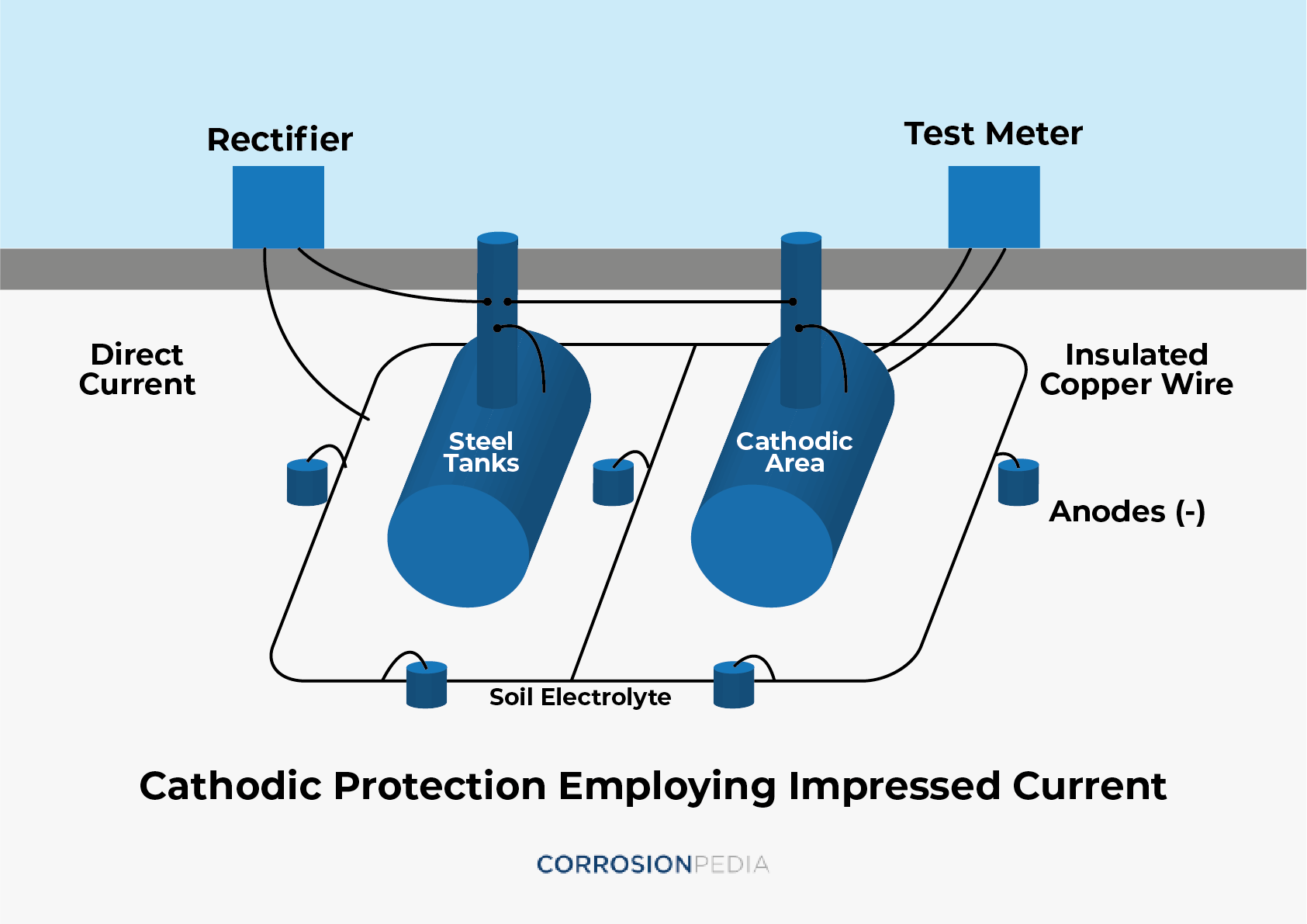
Figure 2. Typical impressed current system.
Function Testing vs. Troubleshooting
Function testing is the test required to ensure the correct operation of any system. In this test, the main functions of the system or its components are checked and, in case of any trouble, the system should undergo troubleshooting. A thorough and well-defined checklist should be used when performing testing.
Troubleshooting any system is how the malfunction of any components may be discovered, allowing for the maintenance of all components and the development of procedures to do so.
Read: An Expert Guide to Accurate Cathodic Protection Measurements
Function Testing of Cathodic Protection Systems
The function of a cathodic protection system is to polarize the protected structure to a certain potential that is more negative than its native one. In order to ensure adequate cathodic protection for any structure, the polarized potential (off potential) of the structure should be measured and compared to a certain criterion, -850 mv for carbon steel vs. a copper / copper sulfate (Cu/CuSO4) reference electrode. The cathodic protection criterion differs according the metal type and the soil resistivity. (Related reading: Practical Techniques for Cathodic Protection Potential Measurement.)
The tools required to measure the potential of the protected structure are:
- A DC voltmeter with high internal resistance
- Copper/copper sulfate reference electrode
- Lead wires
Measuring the potential of the protected structure can be done as follows:
- Locate the reference electrode as close as possible from the protected structure in order to minimize IR drop in the soil.
- Connect the lead wire between the reference electrode and the negative terminal of the DC voltmeter.
- Connect the lead wire between the protected structure and the positive terminal of the DC voltmeter.
- Instantly disconnect the power source of the cathodic protection system through a current interrupter and measure the potential of the protected structure.
If the measured potential is more positive than -850 mv for carbon steel, there is a malfunction of the cathodic protection system. So, troubleshooting the cathodic protection system is necessary.
Troubleshooting a Cathodic Protection System
Troubleshooting a cathodic protection system is to be done for each component of the system, which includes:
- A power source for impressed current cathodic protection
- DC cables
- Groundbed
- Protected structure
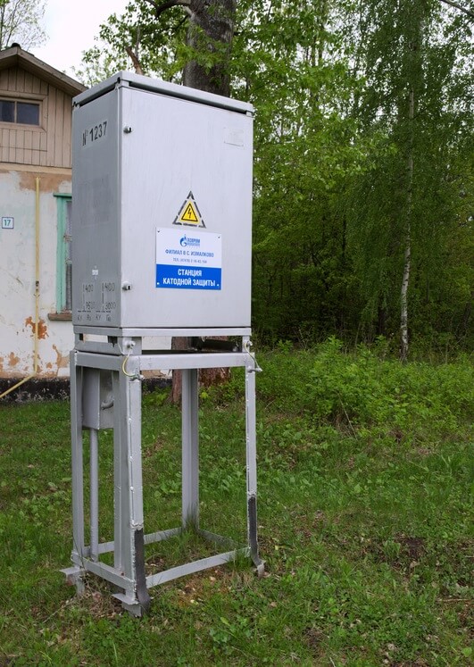
Figure 3. A cathodic protection station. (Source: Shimkovich Svetlana/Dreamstime.com)
Although there are several types of power sources, such as thermoelectric generators, solar power, wind-driven generators, engine-driven generators, batteries or fuel cells, a transformer rectifier is the most common power source used for cathodic protection application.
The main components of a transformer rectifier are:
- A rectifier case or panel
- AC circuit – AC terminals, AC circuit breaker, AC fuse and AC surge protection
- Power transformer
- Rectifying circuit – full wave bridge, DC fuses, DC surge protection and DC output terminals
- DC ammeter and voltmeter with shunt
Normally, the source of trouble in transformer rectifiers may be either in the AC circuit, the DC circuit or the rectifying circuit. In order to determine the source of trouble in the transformer rectifier, the DC output should be measured by a portable multimeter. In case of trouble, the DC output of the transformer rectifier may be one of the following:
Normal voltage, zero current
In this case, the trouble is in the DC circuit external to the rectifier, which are DC cables, positive or negative, or anodes (anodes themselves or splice kits).
0-2 voltage, zero current
In this case, the trouble is in the AC supply or the rectifying circuit.
0.5 normal voltage, 0.5 normal current
In this case, the trouble is in the AC supply or the diodes themselves.
Note that normal voltage is considered to be nearly 15% of the secondary side voltage in the case of a single phase power source.
Troubleshooting DC Cables
DC cables are used for connection between the transformer rectifier DC output terminals and both anodes, the positive cable, as well the protected structure, the negative cable. The source of trouble in DC cables is their discontinuity, which may be due to mechanical stresses in the soil in which they are buried. As mentioned before, DC cables are to be checked by measuring their resistance by an AC voltmeter where the transformer rectifier output voltage is in the normal range and there is no output current.
If a positive cable is the source of trouble, its resistance is very high while the resistance of the negative cable is equal to the sum of the test lead resistance and the negative cable resistance.
If the negative cable is the source of trouble, its resistance is very high, while the resistance of the positive cable is equal to the sum of the test lead resistance and the resistance of the positive cable.
Troubleshooting Groundbeds
Groundbeds consist of a single or multiple anodes connected to the main positive cable through splicing kits or anode junction boxes. The source of trouble in groundbeds may be in the anode tail, the anode connection or the anodes themselves.
Normally, the resistance of anodes increases with time due to corrosion and their interaction with the soil where a passive gaseous layer may form on their surface, as is the manner of high-silicon cast iron anodes in soils rich with chlorines. The resistance of anodes may be also due to the dryness of the soil, which is overridden in the surrounding the anodes by a carbonaceous backfill.
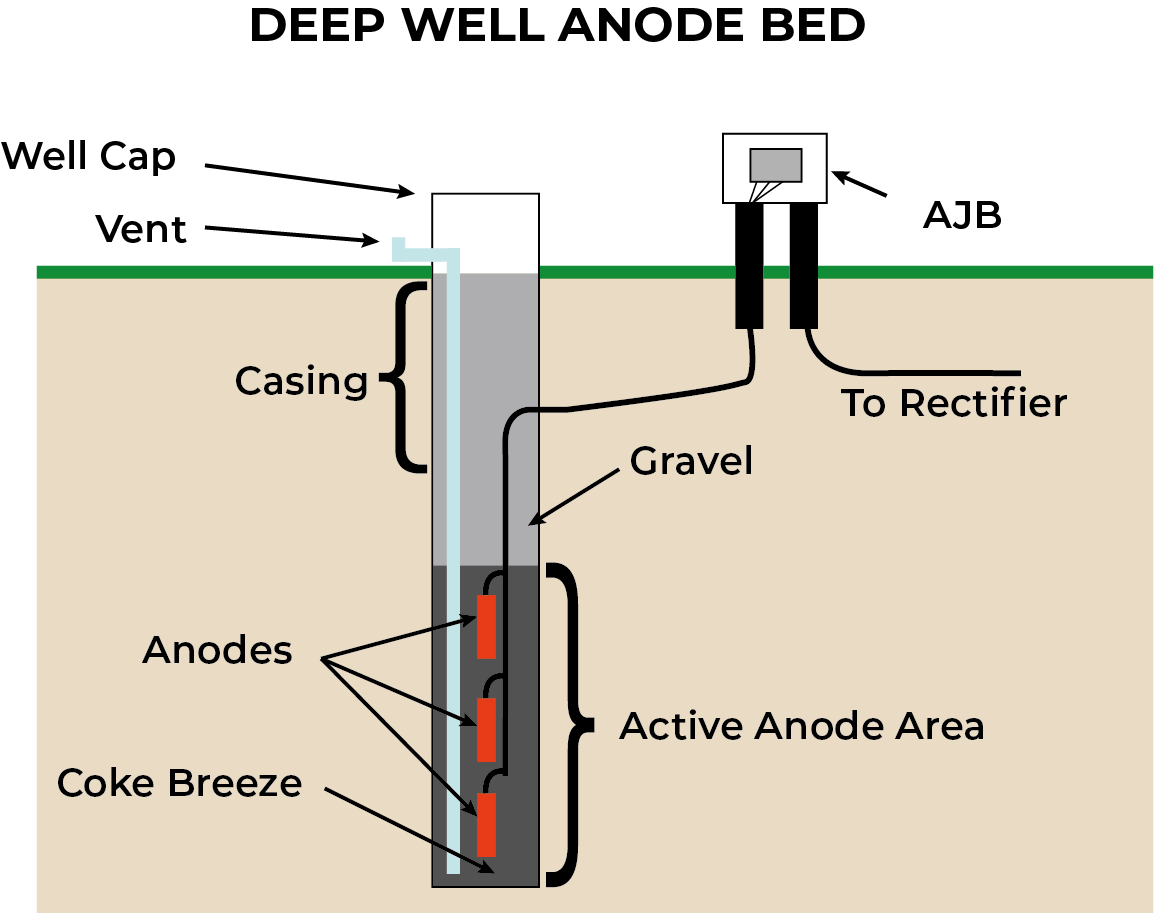
Figure 4. Deep well anode groundbed.
Groundbeds are to be checked when the transformer rectifier output voltage is normal, when there's no current, and when the status of both positive and negative DC cables is good. In case of trouble, the resistance of the groundbed is very high. After determining the groundbed resistance, the measured value is to be compared to the design value and the previously recorded values.
Troubleshooting a Protected Structure
When the transformer output voltage and current are normal, but the cathodic protection criteria isn't achieved on the protected structure, the source of trouble may be abnormal coating deterioration, DC stray currents, shielding, shorts in railroads and crossings casings, or a short in electrical isolation. (For further reading, see Stray Current Corrosion and Preventive Measures.)
In order to evaluate the coating condition or coating efficiency, field surveys need to be done along the pipeline route. This may include a Pearson survey or direct current voltage gradient survey. Coating repairs may be done if required. (Related reading: The Benefits of Timely and Effective Reporting When Conducting Pipeline Close Interval Surveys.)
Cathodic protection shielding may be due to the presence of concrete blocks along the pipeline route. Due to these blocks, the cathodic protection current can't reach the protected structure surface efficiently and, as a result, the criteria of cathodic protection aren't achieved. In this case, removing these blocks is a must if available, but if not, galvanic anodes are to be used to ensure an adequate cathodic protection system.
The cathodic protection current should be measured after and before any cased pipeline to determine if there's any shortage between the main pipeline and the casing pipeline.
Isolating kits may also be tested for shortages and repairs or replacements. DC interference investigations are to be done along the pipeline route so that any stray current problems can also be determined. (For more information about stray currents, read AC Induced Corrosion of Buried Pipelines.)
Periodic inspection of cathodic protection systems is to be done according to certain procedures and schedules. All inspection data is to be recorded and used to aid in troubleshooting.