Pressure equipment is defined as a containment apparatus with a difference in pressure between the internal and external environment. Some examples of pressure equipment are pipelines and pressure vessels that are used to transport and store fluids.
In the oil and gas industry, the most common failure of in-service pressure equipment is due to localized corrosion. This is a major threat because it may cause loss of production, unintentional release, damage to other structures, and injury or fatality to workers and the public.
In 2018, a corrosion failure of a 30-inch oil pipeline led to an explosion and regrettably the death of some workers. The investigation concluded that the corrosion was caused by the breakdown of an external coating. (Get the low down on pipeline failure mechanisms in the article 21 Types of Pipe Corrosion & Failure.) Unfortunately, the corrosion was not detected before the failure. If the corrosion had been detected there were multiple safety guidelines available for the engineer to assess the equipment's condition.
Fitness-for-Service (FFS) of Corrosion Damage
Fitness-for-service (FFS) is a standard and best practice used to determine the fitness of in-service equipment for continued use. There are a number of well-known FFS approaches as shown on Table 1. The most popular procedure is published by the American Petroleum Institute (API) in API 579, which has separate procedures for the assessment of general metal loss (Section 4), local metal loss (Section 5) and pitting (Section 6).
British Standards Institute published BS 7910 to provide guidance for the assessment of flaws in structures. The BS 7910 Annex G procedure covers both general and local metal loss in pipes and pressure vessels but with some differences to that used by API 579 for local metal loss.
| Approach / Standard |
Notable Points |
| API RP579, Chapters 4, 5, 6 |
General, local and pitting corrosion. Primarily design code-based. |
| ASME B31G |
For pipelines. Conservative. |
| British Energy R6 collapse solutions |
Suitable for rapid assessment of circumferential corrosion. |
| BS 7910 Annex G |
Originates from British Gas's procedures for pipelines. |
| DNV RP F101 |
For pipes and piping. Includes partial safety factors and external loads. |
| PD 5500 and ASME code cases |
Considering, for example, use of actual strength rather than SMYS. |
| Reverse Design Code |
PD5500, ASME, etc. Simple. Exploits actual thickness versus code requirements. |
| Shell Global Solutions handbooks for piping, elbows and pressure vessels |
In-house procedures. Combination of methods: RP579, R6 and EPERC. |
Table 1. A variety of approaches and standards.
FFS Methodology and API 579
The thinning of a wall's thickness can be monitored to establish the corrosion rate and the remaining life of the asset. These parameters are considered as part of the prediction and rejection criteria used to ascertain the remaining service life and usage worthiness during corrosion data gathering.
Data collection is obtained from a non-destructive examination (NDE) method such as automated ultrasonic testing. This method can be utilized to inspect a horizontal pressure vessel. (Learn about other techniques in 7 Best Methods for Detecting Leaks in Pressure Vessels.)
Figure 1 shows the results from an automated ultrasonic testing machine that continuously scanned over a suspected corrosion thinning area. The thickness profile at each grid point was recorded for later analysis.
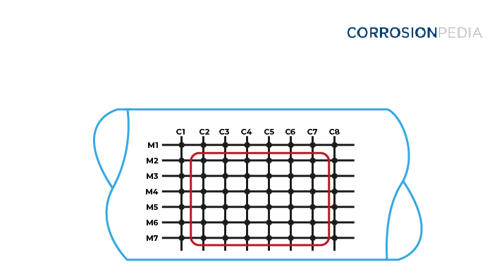
Figure 1. Inspection grid of corroded thinning area.
An estimate of the asset's remaining life can be obtained from following the step-by-step guidelines offered by the API 579 standard. The minimum required wall thicknesses at the circumferential and longitudinal planes are computed with the following mathematical formulas:
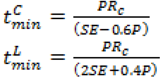
Where:
E = weld efficient factor
S = allowable stress
P = maximum design pressure
R = pressure vessel radius
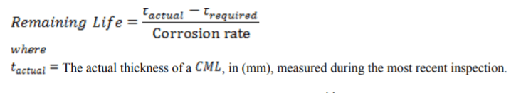
These two numbers are then compared with the average measured thicknesses that are obtained from the results of ultrasonic testing. The remaining life of the pressure vessel is determined by factoring the rate of corrosion and the time period between measurements with the equations shown below. (Related reading: Corrosion Rate Conversion: Simple Ways to Convert Data Between Common Corrosion Units.)
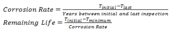
or by the formula:
Beware of Structural Discontinuities
FFS assessment procedures have a limitation because they are almost always derived from a simple straight pipe that does not take discontinuities into account. At the location where there is a change in geometry (such as the head and shell joint), there is an increased bending moment caused by displacement incompatibility. From the free body diagram shown on Figure 2, the effect of shear forces and moment results in a radial displacement.
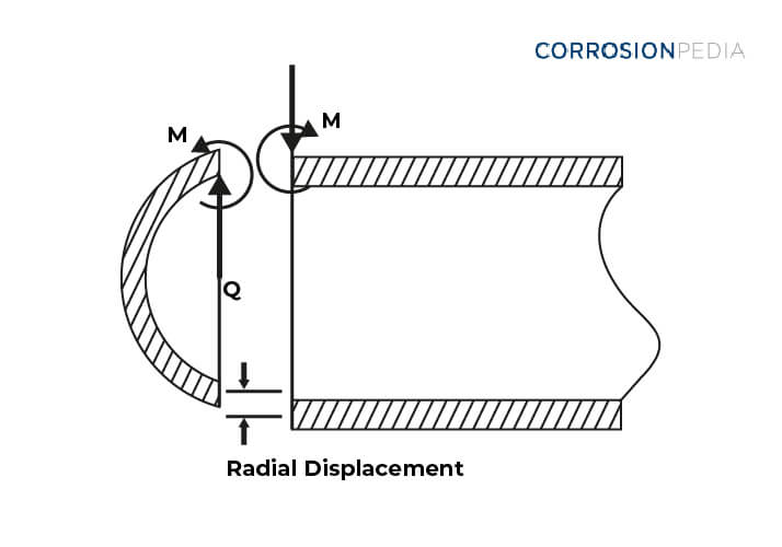
Figure 2. Loadings at the discontinuity located at a head to shell joint.
In addition, structural discontinuities present additional challenges because they have not been adequately validated by burst test data. It is recommended that asset owners ensure that the responsible contractors have the finite element analysis (FEA) experience or validation cases for these geometries.
Structural discontinuity problems are often very difficult to solve analytically, sometimes impossible.
Accounting for Discontinuities at Nozzles
The stress profile for a nozzle is even more complex than at other discontinuities. The principle stresses at the inside surface of the corner are in the axial plane of the main shell as shown in Figure 3. API 579 has adapted the area replacement rules (i.e., reverse design) to prevent global failure of a corroded nozzle, but this does not explicitly safeguard against local collapse of the corroded ligament.
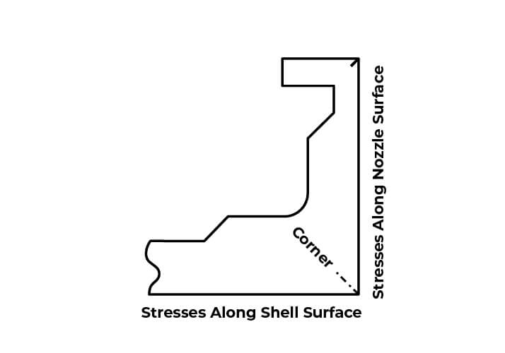
Figure 3. Complex principle stresses along the shell to nozzle joint.
To avoid global collapse of corroded nozzles, the following available methods can be followed:
ASME VIII Division 1 "area replacement rule"
The Welding Research Council's method (WRC 107), or
The BS PD5500 elastic stress design rules.
The choice of assessment depends on the input parameters available and which method will ensure the integrity without being overly conservative. However, the use of global collapse criteria is not always sufficient to ensure fitness for service and no standard method of nozzle corrosion assessment has been universally accepted worldwide.
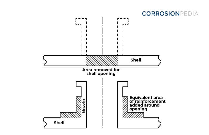
Figure 4. Area replacement methodology to ensure adequate global nozzle strength.
The Future of Corrosion FFS Procedures
Code committees in the United States and Europe continue to build on each other’s experience so the future of FFS is likely to be the combined lessons learned from the synergy. Endorsement from API, BSI and other standards in the near future will enhance user’s confidence and encourage a wider application.
At this time API 579 and BS 7910 are the most commonly used procedures. The application of API 579 is intended for American Society of Mechanical Engineers (ASME) equipment. Application of API 579 on other equipment requires careful interpretation of the procedures.
BS 7910 can be applied to a wider type of equipment because it is written in a more generalized manner without reference to a particular industry-specific design code. Although users can use their judgement, BS 7910 still requires some technical expertise at all levels of assessment, with the level of conservatism decreasing with increasing assessment level.