Corrosion is an electrochemical reaction that can be stopped by lowering the electrical potential of the metal to below that at which it can corrode. Cathodic protection (CP) monitoring measurements are concerned with the equilibrium of electrical potentials. This device establishes that equilibrium by detecting the direction of corrosion current.
Introduction
DC current is proportional to metal loss in a corrosion reaction, but practical application of cathodic protection makes it impossible to measure the exact amount of current distributed through the electrolyte to any part of a structure. Pipelines are sectionalized, with isolation joints, to enable some control of the protective current, but each section will include many interfaces between the metal and the electrolyte. Each of these interfaces can have different chemical and electrical properties, affecting the distribution of the cathodic protection current. Each interface can be the whole or part of a corrosion cell and there are, therefore, many corrosion reactions taking place on any pipeline section.
We need to know that the corrosion current has stopped at each of these interfaces before we can say that cathodic protection has been achieved.
Current is only measurable in a “closed circuit” condition, but each of these reactions passes current into “mass earth” and receives current from “mass earth”. It follows that the practical application of cathodic protection makes it impossible to measure the exact amount of current distributed from mass earth to any single corrosion cell on the pipeline section.
Cathodic Protection
Cathodic protection attempts to lower the electrical potential of the whole of the pipeline to below its “corrosion potential”, but this will only be effective if it is in relation to the potential of the electrolyte at the immediate interface with the metal. (Gain an introduction to CP in the article The Basics of Cathodic Protection.) The potential is measured as a voltage (potential difference). An example of the application of this type of measurement may be seen in the Daniell cell, which is used in laboratories to ascertain the equilibrium of corrosion reactions.
In the practical application of cathodic protection, the potential of the whole pipeline is almost uniform because of the low resistance of metal to an electrical current. This is only apparent if measured against a single reference electrode, in a fixed position, using a long conductor to contact the pipeline at a variety of locations.
Ground Potentials
The potential of the ground (earth or water) varies considerably and there are several techniques to plot the potential “gradients” or “IR drops in the soil”. There are many causes of these potential gradients, one of which is the passage of the cathodic protection current itself. Readings as high as 2 or 3 volts can sometimes be measured between two zones in the ground. The causes of these potentials can overlay each other and at least six causes of such interference are readily demonstrable. At some locations, the potential of the ground is forced up by some sources and down by others, while other sources cause fluctuations and surges.
These manifestations have been called interference currents or stray currents and some have an effect on the corrosion reaction, but others simply cause errors in the readings (on the meter). (Learn more in Corrosion and Electrical Interference in Buried Metallic Structures.) It is possible to evaluate each of these effects in any location, using multi-channel voltage recorders and complex procedures. This is very interesting but has little practical use as we simply need to know if corrosion has stopped.
Electrical Currents in Pipelines
Pipelines are sectionalized, using isolation joints, to enable some control of the protective current, but each section will include many coating faults, which are individual interfaces between the metal and the electrolyte.
Each of these interfaces can have different physical, chemical and electrical properties, affecting the distribution of the cathodic protection current. We need to know that the corrosion current has stopped at each of these interfaces before we can say that cathodic protection has been achieved. The corrosion current will pass through the pipeline metal from the cathode to the anode, from which it passes into the earth electrolyte. The direction and strength of the currents within the metal depend on the location and size of each coating fault as well as the EMF generated by each individual corrosion reaction. They also depend on the resistances and opposition potentials encountered in the electrolyte, which is the return path of the corrosion circuit.
Monitoring Methods
1. Conventional Approach
It is, therefore, physically impossible to measure the corrosion current at each interface, and the industry has adopted “pipe-to-soil potentials” as a means of monitoring the corrosion reaction. Unfortunately, these are really voltage measurements that simply show a general relationship between the whole of the pipeline and the position in which the earth-connection electrode is placed.
2. European Continental Approach
This has been recognized by many scientists in continental Europe and some have marketed devices incorporating a steel/earth contact with an electrode. These devices are connected to the pipeline and the electrode can be regarded as a standard reference because the arrangement of the device ensures a constant physical relationship, which is necessary in measuring reaction potentials.
The Alexander Cell
This device works on exactly the same principal as a long-term weight loss corrosion coupon, but has the advantage of giving an immediate result, based on Faraday's Law, which relates the amount of current to the weight of metal going into solution.
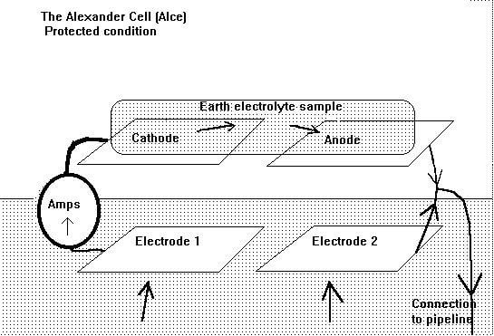
The Alexander cell consists of four steel electrodes forming a DC circuit, driven by the corrosion reaction between bright steel and a sample of the local electrolyte. It is in fact a corrosion cell, similar to the Daniell cell, which is a standard piece of laboratory equipment used in the study of the thermodynamics of corrosion. The circuit of the Alexander cell includes an earth path, which allows the whole corrosion cell to be influenced by the current, locally available from the cathodic protection system. The effect of this influence can be seen on a current meter in a closed circuit condition.
Alexander Cell Arrangement
Two of the electrodes are on the top of the device and the other two form the base. One of the top electrodes is cleaned, to bright metal, before use, and the other remains untreated.
The corrosion reaction takes place on the surface of the bright steel electrode (anodic) on top of the device when a sample of electrolyte is placed to bridge the gap to the (cathodic) passive steel.
The current then passes through the meter to the first electrode in contact with the ground.
Both base electrodes are cleaned to bright metal before the test to ensure an equal reaction to the earth electrolyte.
The circuit is complete when the corrosion current enters the second electrode in contact with the ground, which is connected to the bright steel electrode on top of the device.

A connection is provided to connect the whole cell to the pipeline in such a way that the cathodic protection current may influence both cathodic and anodic interfaces, as it would in the case of a natural corrosion cell on the surface of the pipe.
The Equilibrium of the Cell
When the ALCE is placed on the ground and charged with a sample of the electrolyte, the corrosion reaction produces a current that is a component of the dynamic equilibrium the cell.
The bright steel bases have an equal reaction, as they have both been cleaned to the same condition.
The anodic electrode, on top, is above its corrosion potential and the cathodic electrode must be at a lower potential if a current is observed.

When the ALCE is connected to the pipeline, it allows cathodic protection current to follow this path to the negative terminal of the transformer rectifier, which is designed to lower the pipeline to below its corrosion potential. If there is insufficient cathodic protection current density in the locality, then corrosion will continue, possibly at a lower rate.
If there is sufficient current density in the vicinity, then the cathodic protection current will oppose the corrosion current and flow through the Alexander cell anodic path to the pipeline. This can be seen on the ALCE meter by the change in current direction.
Computer Model
It is possible to make a working model of the Alexander cell on a computer worksheet such as Microsoft Excel for Windows.

This model works in conjunction with a model of a complete cathodic protection system showing four corrosion cells on a single length of pipeline. These corrosion cells react to the output of the cathodic protection transformer rectifier (TR). The dynamic equilibrium of each cell is shown in the actual potentials that the computer calculates. The user can put values to the reaction EMF and to the output of the TR. It will be seen that it is possible to stop the corrosion reaction within the Alexander cell by adjusting the TR in the model.
The Alexander cell simply depends on Faraday's Law, which relates the amount of metal going into solution, to the amount of current flowing from the metal to the electrolyte. In the computer model, it is related to the potentials of all its components.
Procedure to use the Alexander Cell
- The two base electrodes are cleaned to bright metal and placed on the ground, as close to the pipeline as possible.
- The anode (on top) of the cell is cleaned to bright metal and the meter is connected in circuit.
- A sample of the pipeline backfill is positioned to bridge the two electrodes on top of the cell, but in isolation from the ground. This completes the measuring circuit and a current can be seen on the meter.
- The strength and direction of this corrosion current is noted.
- The cell is connected to the pipeline, while watching the meter, and the changes in the behavior of the current are noted.

Interpretation
The reactions at the two base electrodes are similar and their potentials are balanced.
The reaction between the anode and the sample of electrolyte causes the current to flow through the measuring circuit.
The potential of the bright steel anode is made equal to that of the pipeline through a low-resistance conductor.
If this new potential is sufficiently low, the current will reverse direction through the Alexander cell meter. The reaction at the interface cannot continue, as current cannot pass in both directions at the same time. Micro cells on the surface of the anode will also be lowered below their corrosion potential and be passive, according to the laws of thermodynamics.
As the corrosion reaction is the sole cause of the original reading on the meter, then it may be safely reasoned that the reaction has stopped when this current has stopped.
Any current flowing in the opposite direction must be that resulting from the connection to the pipeline, as there has been no other alteration to the measuring circuit.
This current is seen to be passing against the corrosion current—which must, therefore, have been stopped. The current passing onto the pipeline is returning to the negative terminal of the cathodic protection source. In this way, the ALCE demonstrates that there is sufficient current density at this location to prevent corrosion current passing from the anode of a corrosion cell into the electrolyte.
If there is no current being discharged from the metal to the electrolyte, then no metal can go into solution (Faraday).