In order to determine the adequacy of a cathodic protection system applied on a certain structure, its polarized potential has to be measured. (For an introduction to cathodic protection, read The Basics of Cathodic Protection.) The polarized potential is the summation of corrosion potential and the amount of polarization that the structure has, excluding the soil IR drop.
Polarized potential is the potential across the structure-to-electrolyte interface. Below, we will talk about the practical techniques that can be used to measure a structure’s polarized potential.
1. Current Interruption Technique
The soil IR drop can be excluded from the measured potential by interrupting the cathodic protection (CP) current source instantaneously. This can be done by installing a current interrupter at the CP source and adjusting the ON and OFF cycles. One should make sure that the OFF cycle is as short as possible to avoid structure depolarization, yet long enough to be able for reading records.
It’s important to know that this technique is very simple for application in limited systems, but it faces many challenges when applied in large networks. These challenges include:
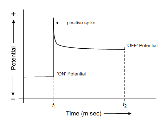
- Positive Spiking
When the current is interrupted, a positive spike occurs in the measured potential due to the inductive and capacitive effects of the pipeline, which doesn’t represent the true potential of the pipeline. The duration of this spike may be 0.3 seconds. So, the instant OFF potential reading, which represents the polarized one, should be recorded after this time has passed.
- Interruption of all Current Sources
This happens in large networks of pipelines, where there are many current sources distributed at different sections of the network, as well as in urban areas, where pipelines of different authorities run with a lot of parallelism and crossings—and so stray currents exist in pipelines. (To learn more about stray currents, see Stray Current Corrosion and Preventive Measures.) Current interrupters should be installed at all CP sources and synchronized so that the CP current can be interrupted at the same time and then all IR drops can be eliminated. When synchronization of current interrupters can’t be done, the total IR drop can be computed by taking the summation of individual IR drops. Synchronization of current interrupters can be achieved by using GPS-synchronized interrupters, which take the same signal from the satellite. However, if signal is lost at any interrupter, the measured potential will not represent the true one.
- Recirculating Currents
Recirculating currents are post-interruption currents that are generated between highly polarized locations and lesser polarized locations. Due to these currents, the measured potential at highly polarized locations is more positive than the true one, while at less polarized locations the measured potential is more electronegative than the true one. The error in measured potential due to these currents is ± 150 mv.

2. Reference Electrode near the Structure
By placing the reference electrode as close as possible to the protected structure, the soil IR drop can be minimized. The reference electrode should not be too close to the structure so that it doesn’t eliminate the CP current; it is recommended to be at a distance of twice the reference electrode diameter.
This technique is impractical for buried pipelines, except at places where the pipeline enters or exits from the ground. This technique can be used for underwater pipelines.
For coated pipelines, if the reference electrode is placed close to the pipeline and near the coating, the IR drop can’t be minimized. The reference electrode would need to be placed close to the coating holidays for accurate measurements, which is not practical.
Inside water storage tanks, the electrode should be positioned as close to the wall of the tank as possible. The same is true for waterfront and offshore structures; the electrode should be as close to the piling as possible. In moving water, the electrode may swing about, so some structures are equipped with guide wires or perforated plastic ducts to restrict the movement of a portable electrode.
For on-grade storage tanks, data are frequently taken around the periphery of the tank. This may not yield accurate data about the potentials under the tank bottom, particularly if the anodes are in a ring around the tank or the tank is large in diameter. Stationary reference electrodes under the tank bottom yield the best data. Alternatively, if a perforated plastic tube is installed under the tank and filled with water, a reference electrode can be pulled through it and potentials measured at intervals underneath.
An alternative to placing the reference electrode close to the structure is to install a plastic tube filled with soil from the grade next to the pipe surface and put the reference electrode in it.
3. External CP Coupons
CP coupons are intended to simulate a small portion of a well-coated pipeline like a holiday; they are manufactured from the same alloy as the protected structure, and they are typically 10 to 100 cm² in surface area.
CP coupons should be buried near the protected structure in the same electrolyte, subjected to the same CP current and connected electrically to the protected structure.
 CP coupons can be used to determine the corrosion rate of the structure or to monitor the adequacy of the applied CP system.
In order to determine the corrosion rate, the coupon needs to be weighed beforehand and then buried and connected to the structure. After a certain time, the coupons should be removed and weighed. The corrosion rate is the weight loss per time.
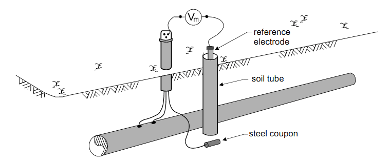
For monitoring of CP potential, the connection between the coupon and the pipeline needs to be interrupted instantaneously and the reference electrode should be placed in a soil tube to eliminate any IR drop in the soil. So, the polarized potential of the coupon can be measured with respect to the reference electrode placed in the soil tube. If the polarized potential of the coupon is -850 mv/cse or more negative, any holiday of the same size or smaller will be equally well protected.
The above techniques are the most practical ones used for potential measurements, but in order to obtain correct measurements, proper instruments have to be used. These techniques are very important for any structure-to-electrolyte potential survey.
***
Related article:
An Overview of Cathodic Protection Potential Measurement