Due to limited public lands, we sometimes find ourselves in a situation where it is necessary to install direct current (DC) electrical transmission systems in close proximity to buried pipelines. This could cause a problem for the pipelines in the form of stray current corrosion. In this article we will explain stray current corrosion, how it occurs and the necessary steps to to mitigate the problem.
What is a Stray Current?
In common parlance, stray is defined as "to deviate from the direct course, leave the proper place, or go beyond the proper limits, especially without a fixed course or purpose. In electrical engineering terms, stray current is a current that is flowing on a path that is not the intended path on which it should be flowing. Stray currents are inevitable, and they can be either static (nonvarying) or dynamic (varying).
In corrosive environments, the stray currents responsible for pipeline corrosion are direct currents flowing through the earth from a source other than those associated with the affected pipeline. In the next section we will explain in more detail how stray currents can cause corrosion of pipelines or other buried structures.
How Stray Current Corrosion Occurs
Stray currents associated with pipeline corrosion are currents that flow from an outside source to one area of the pipeline and then flow along the pipeline to some other area where they exit the pipeline to reenter the earth. This results in DC corrosion and completes the circuit by returning to the original DC power source.
Areas where the current enters the pipeline from an electrolyte are termed cathodic sites, and no corrosion will occur in these areas. The problem with a stray current is mainly in areas where the current leaves the pipeline and enters the electrolyte before returning back to the current source. These areas are termed anodic sites, and are areas where corrosion occurs.
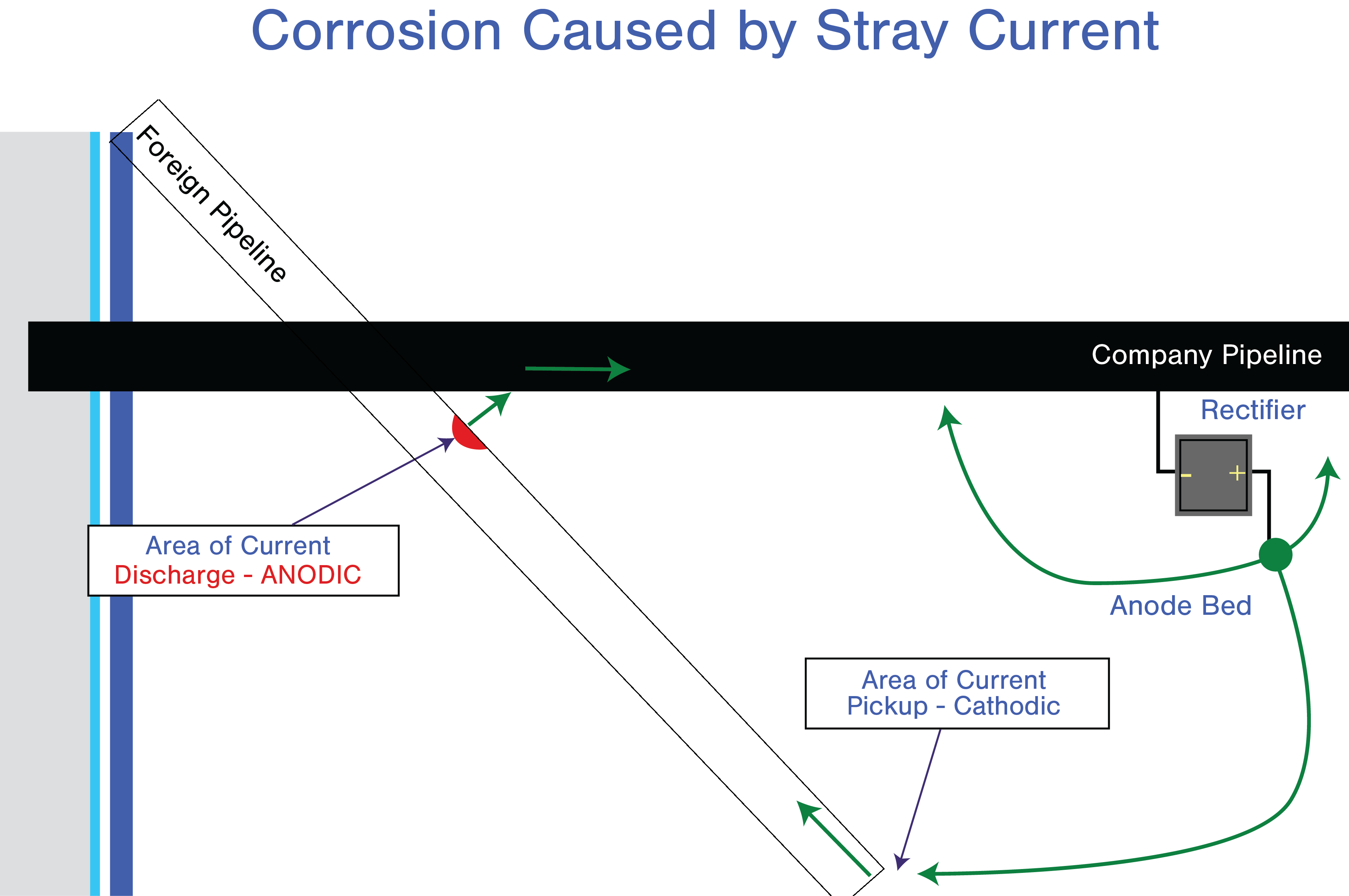
Figure 1. Diagram of stray current corrosion.
Sources of Stray Currents
There are many potential sources of stray currents. Some examples are:
In this article we will be focusing on stray current corrosion caused by DC transit system. We will explain how it occurs, how to detect its presence and how to mitigate it. (For more information on other sources, see Corrosion and Electrical Interference in Buried Metallic Structures.)
DC Transit Systems as a Source of Stray Current Corrosion
Stray current corrosion due to DC transit system is a very important issue where the responsibility for addressing the issue usually rests with the pipeline owner. That's mainly due to the severity of stray current corrosion from DC transit systems and the complexity of solving this problem due to the nature of the exposure because the DC load is always varying.
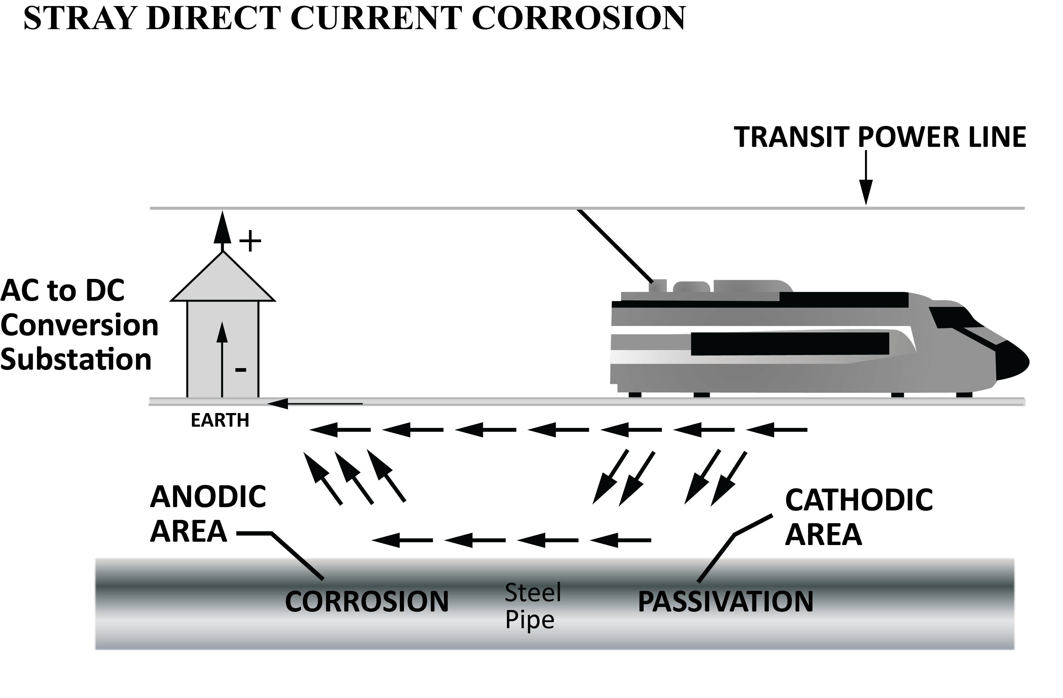
Figure 2. Stray current corrosion from a DC transit system.
In normal conditions, the DC transit system is operated through the insulated feeder, which is connected to the positive bus of the DC traction power substation. The operating current (which can reach in the range of kilo amperes) is returned back to the substation via the tracks (the running rails) that are connected to the negative bus at the substation. However, because the tracks (the return path) are laid on the ground and not insulated, some of the returning current leaks into the ground, where it will find a lower resistance path through the neighboring pipeline buried near the DC transit system. This leaking current, or what we call stray current, will enter the pipeline at one point and will flow through the pipeline until it finds a point where it will leave the pipeline and enter the earth again in order to reach the negative bus of the substation.
The area where current enters the pipeline is called the pickup area or the cathodic area, and no corrosion will occur at this point. However, stray current corrosion occurs at the point where the current leaves the pipeline and reenters the earth; this point is called the discharge area or the anodic area.
How to Test for the Presence of Stray Currents from a DC Transit System
Detecting the presence of a stray current from a DC transit system is accomplished by using stray current mappers or high impedance data loggers. Readings from the data loggers should be time-stamped and will be used to measure the pipe-to-earth potential readings.
The pipe-to-earth potential readings should be compared to the time schedule of the DC transit system in order to correlate the data logger readings with the transit system's operation. This ensures that the change in the pipe-to-earth potential is in fact due to a stray current from the DC transit system and not from another source.
Locations where tests may be conducted should be based on a previous history of all pipeline routes as well as those of the DC transit system. As a preliminary test, pipe-to-soil potential readings should be measured at the vicinity of DC transit power stations because these are the most suspected sections to be affected by stray current activity, especially if the substation is grounded.
Further tests should be done in other pipeline locations because the pipeline may be exposed to stray currents in other locations due to low track-to-earth resistance values.
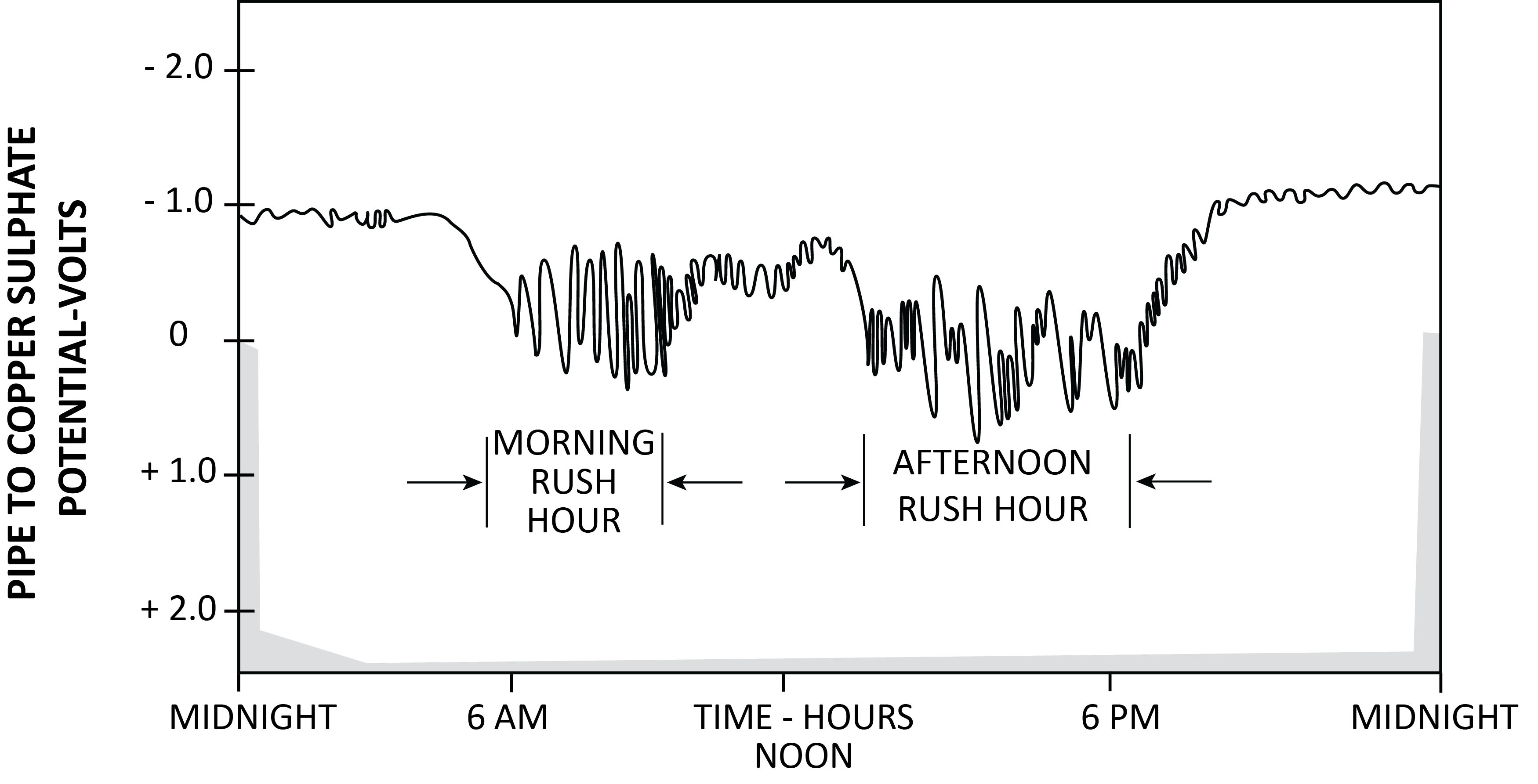
Figure 3. A simplified example of pipe to soil potential readings to confirm the existence of a stray current.
As shown in Figure 3, the stray current activities are related to the morning and afternoon rush hour. The duration and extent of exposure should be the deciding factor in determining if mitigation measures should be taken or not. If the pipeline is found to suffer from a large amount of stray current activity for an extended period then mitigation actions must be promptly adopted, otherwise there is a high probability of pipeline corrosion in a very short time.
How to Mitigate Stray Current Corrosion
Several methods are used to mitigate the effect of stray currents as described below. (Related reading: Stray Current Corrosion and Preventive Measures.)
Electrically isolating the rails and substation
It has been proven that increasing the rail-to-earth resistance reduces the stray currents flowing to the pipeline. This can be accomplished by installing insulating pads between the rails and ties and between the hold-down plates and the rails. Moreover, the negative bus of the substation should be isolated from the grounding system.
Although this approach has proven effective in reducing stray current activity, it has the disadvantage that these insulation materials must be checked periodically to ensure that they have not deteriorated. Also, switching devices should be installed between the rails and the grounding system to connect the rails to the grounding system if a certain rail voltage to earth is achieved.
Electrical bonds
A direct electrical bond can be made between the pipeline and the negative bus of the DC transit system substation to provide an electrical path between the pipeline and the substation. However, this approach has the disadvantage of reducing the overall resistance between the rails and the earth. This will increase the stray current picked up by the pipeline, which otherwise would not occur if the direct bond didn't exist. This could be damaging to pipelines with electrical discontinuities such as iron water mains that will corrode at the insulating joints.
Reverse current switches
In the case of a DC mass transit system, the same point on the pipeline can be both a pickup and a discharge depending on the location and movement of the transit vehicle. Because of this fluctuation, any connection between the pipeline and the transit system must restrict the current flow to one direction. This can be accomplished by installing diodes or relays in the bond between the two. A summary of various reverse current switches and their characteristics is shown in Table 1.
| Switch Type |
Characteristics |
| Electromagnetic (relay) |
Requires AC power to operate the relay; relay must conduct all current; may be slow to open. |
| Diodes (germanium, silicon) |
Requires a minimum of 0.4V to conduct; have resistance; subject to surge failures and reverse voltage breakdown. |
| Hybrid (relay in parallel with diodes) |
Smaller relay required because diodes carry most current and are subject to reverse voltage breakdown. |
| Potential controlled rectifier |
Can drain all the stray current but are relatively expensive. |
Table 1. Common reverse current switches and their characteristics.
Cathodic protection
Although cathodic protection (CP) is known as an effective method to mitigate the effect of stray currents, their use for DC transit systems is unfavorable because of the large quantities of stray currents. Therefore, the use of galvanic anodes is precluded and ICCP is preferred. (Watch the video: When to Use Impressed Current Cathodic Protection.)
Unfortunately, using large ICCP systems in urban areas to mitigate stray currents could cause an interference problem in another facility; therefore, using galvanic or impressed cathodic protection systems is impractical as a stray current corrosion mitigation method.
Forced drainage bond (potential controlled rectifier)
This is considered the most successful method to mitigate the effect of DC transit stray currents.
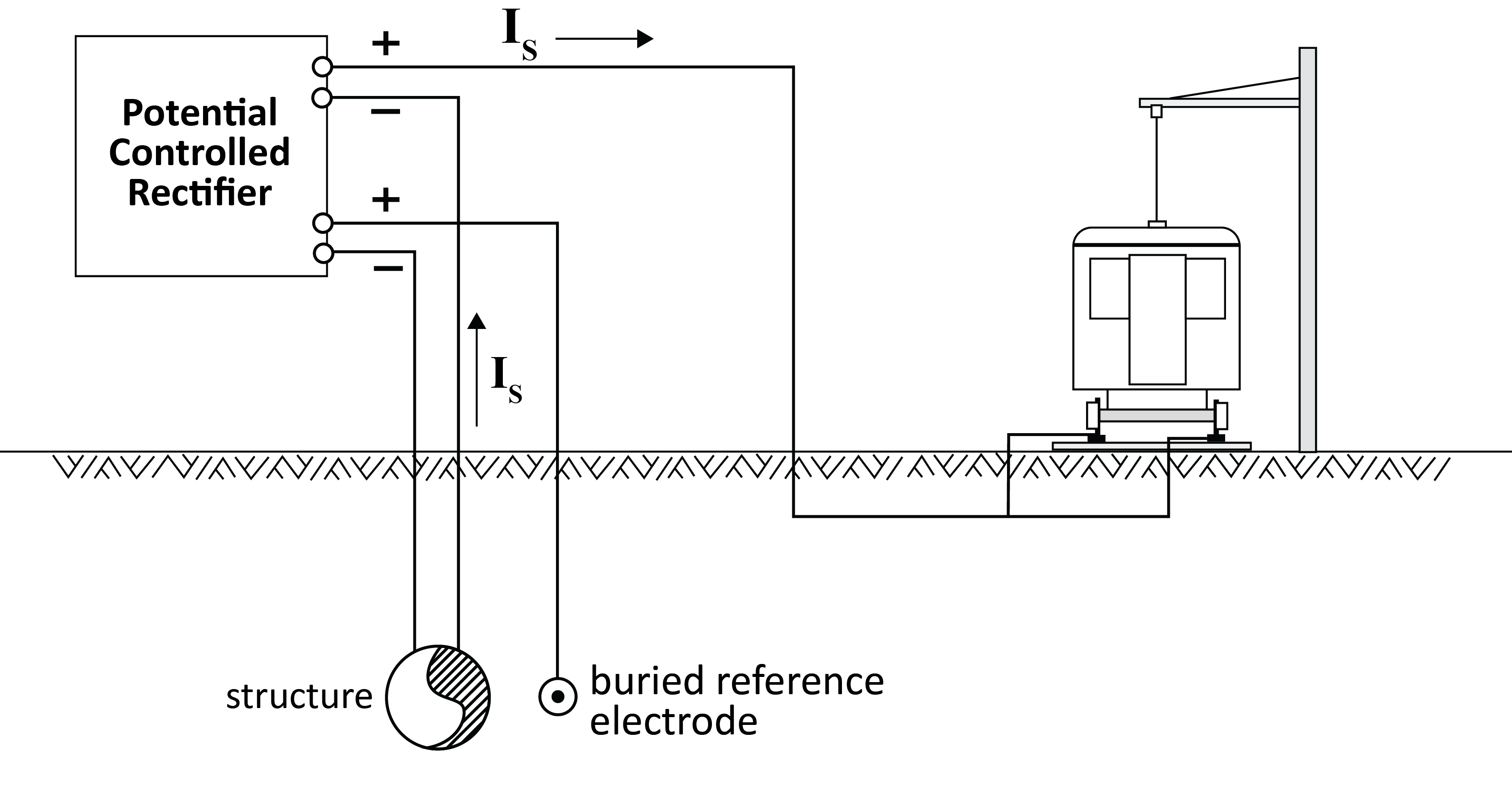
Figure 4. Diagram of forced drainage bond.
The voltage output of the controlled rectifier is controlled by the potential difference between the structure and the buried reference electrode. If the structure's potential measured with respect to the buried reference electrode becomes more positive than a predetermined set point, then the controlled rectifier will force more current through the bond to lower the structure's potential to be lower than the predetermined set point. The main disadvantage of this mitigation method is it's higher cost compared to other mitigation methods.
Conclusion
Stray current corrosion from DC transit system is becoming a greater concern for pipeline owners as urbanization continues and more large infrastructures are built. Due to its extremely harmful effects, the presence of stray currents should be ascertained and their source identified. This can be done by measuring the pipe-to-soil potential using time-stamped high impedance data loggers.
After determining the presence of a stray current, the pipeline owner can choose the most suitable mitigation method to use on his pipeline system. The most effective mitigation method is the forced drainage method, but it's relatively high cost is considered a disadvantage compared to other methods.
Finally, we can say that stray current corrosion is a real threat to the integrity and safety of buried pipelines and infrastructures. Pipeline owners must be alert and invest in monitoring tools to detect the presence of stray currents and mitigate them.