Content provided by PPG.
On the morning of July 17, 2007, a solvent storage tank at a Barton Solvents facility in Valley Center, Kansas exploded and caused a fire that spread to nearby storage tanks, triggering further explosions and fires. Within minutes the entire tank farm was destroyed. (To learn more about tank farms, see Cathodic Protection of Earthed Tank Farms.)
The first explosion occurred inside a storage tank containing Varnish Makers’ and Painters’ (VM&P) naphtha, which is a non-conductive flammable liquid used to manufacture coatings. Non-conductive materials have a volume resistivity greater than 109 Ω•m3. At the time of the explosion, a tanker truck was transferring naphtha from one of the truck’s containers into the storage tank. From the beginning, static electricity was thought to play a role in the incident.
How Static Electricity Charge Accumulates
A liquid flowing through pipes and valves tends to cause a buildup of static electricity, a process known as charging by transport. The static electricity results from a charged liquid flowing past a dissimilar material (in this case the inside walls of the pipes and valves) and transferring electrons to the other material. The static electricity’s charge rate is a function of the flow rate.
It should be noted that charges are never generated or created because the electrons already exist; they can, however, accumulate or build up. Only non-conductive liquids show charging by flow. Water, which is a conductive liquid, does not charge by flow.
As a non-conductive liquid flows into a storage tank it carries an electrical charge with it, which can accumulate in the tank if it is not properly grounded. Turbulence or stirring can increase the charge accumulation. Later, sudden static electricity discharges may occur in the form of sparks.
Fortunately, sparks can be prevented if all parts of the system are bonded (connected by an electrical conductor) and grounded.
Determination of the Incident’s Root Cause
The United States Chemical Safety Board (CSB), an independent government agency that examines industrial chemical incidents, performed an investigation and released its report in September 2008.
The CSB learned that on the morning of the incident a tanker truck arrived at the facility to transfer its load of naphtha into an outdoor storage tank.
As is typical, a grounding cable was connected between the truck and an electrical grounding station. All the equipment involved was bonded (connected together with electrical conductors) and grounded.
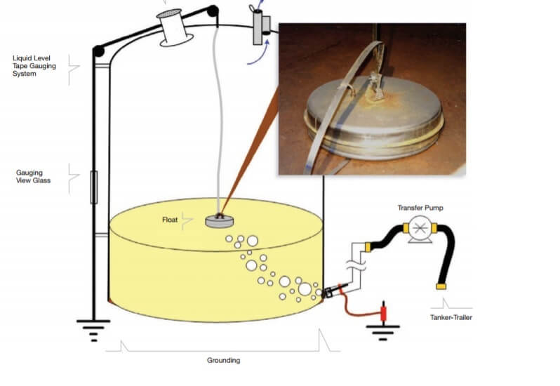
The storage tank contained a device designed to measure the level of the liquid solvent inside the tank. The device consisted of a float riding on the solvent’s surface that was connected to a metal tape that exited the top of the tank and wound through pulleys through a gauge viewing glass and to a ground connection (Figure 1).
 Image: PPG
Figure 1. Diagram of storage tank with float and loose linkage assembly connected to metal tape.
The linkage between the metal tape and the float was designed to have some slack so the float could bob on the surface (like a fishing bobber) when solvent was added to or removed from the tank.
The tanker-trailer truck had three individual compartments that were emptied in succession. Unfortunately, air entered the transfer hose as the hose was moved from one compartment to another, introducing air and turbulence inside the storage tank.
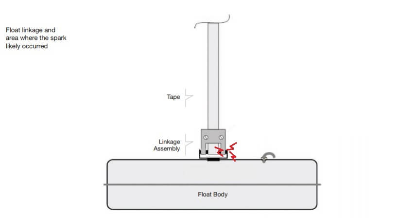
While the space above the solvent began filling with an explosive mixture of vapor and air, the turbulence occasionally caused excessive slack in the metal tape and a loss of electrical conductivity in the linkage assembly between the float and the tape as the float rocked back and forth. As a result there were brief periods when all of the components inside the tank were not bonded or grounded. Over time the metal float accumulated an electrical charge (Figure 2), and at some point a spark ignited the vapor-air mixture.
 Image: PPG
Figure 2. Float linkage assembly and area where the spark likely occurred.
The resulting massive explosion was sufficient to throw the storage tank into the air and beyond the boundary of the tank farm. Two nearby tanks ruptured and burst into flames. The spreading fire caused the remaining tanks in the farm to over-pressurize or ignite. Heavy lids flew off the tanks. It was estimated that 20,000 gallons (76,000 liters) of flammable chemicals were released into the surrounding containment area. Various metal parts were hurled large distances into a residential neighborhood. A mobile home about 300 feet from the tank was struck by a tank lid and a pressure valve hit an adjacent business about 400 feet away.
The CSB concluded that several factors combined to cause the incident:
- The usual bonding and grounding methods commonly used at that time may be insufficient. Specifically, loose linkage assemblies like those connecting the float to the metal tape should be modified (possibly with the addition of a fixed bonding/grounding wire) so they remain grounded at all times.
- Companies need to take extra precautions when handling flammable non-conductive liquids, which tend to accumulate static electricity. Although some standards exist (Table 1), they may not be comprehensive enough to address the special case of non-conductive flammable liquids.
- Repeatedly stopping and starting the solvent transfer caused air and turbulence to be introduced into the tank. This and the likely presence of water and sediment in the tank contributed to the static charge accumulation.
- Even though the tank itself was grounded the static charge accumulated faster than it could be dissipated because naphtha is a poor conductor.
- Liquids such as naphtha, benzene, xylene, toluene, heptane and hexane form vapor-air mixtures that can easily ignite in certain conditions.
- Some material safety data sheets (MSDSs) do not list all of the relevant hazards that non-conductive flammable liquids pose, such as their tendency to accumulate static electricity during transfer and storage.
|
Region
|
Standards
|
|
EMEA (Europe, Middle East and Africa) tank construction standards
|
EN 14015: Specification for the design and manufacture of site built steel tanks
API 650: Welded tanks for Oil Storage
|
|
Western and Southern Europe established requirements to avoid static electricity
|
Operation guidelines (CLC/TR50404) Electrostatics
Code of practice for the avoidance of hazards due to static electricity
|
|
Germany
|
DIBt (coating related) Deutsches Institut fur Bautechnik
|
|
Eastern Europe
|
Local/government guidelines/requirements (coating related)
|
|
United States
|
American National Standards Institute (ANSI) Z400.1
Occupational Safety and Health Administration (OSHA) 1910.303
National Fire Protection Association NFPA 77
|
Table 1. Regional standards regarding static electricity.
Hazardous Ignition Triangle
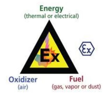
The hazardous ignition triangle is a diagram that indicates the three ingredients required to cause an explosion (Figure 3). In the case of the explosion in Kansas, the three ingredients were:
- A source of energy – static electricity
- An oxidizer – air above the naphtha inside the tank
- A combustible fuel – naphtha vapors
 Image: PPG
Figure 3. The ignition triangle.
An explosion cannot occur if any one of the three ingredients is removed from the scenario.
Designs to Prevent the Ignition Triangle
Proper and comprehensive designs can prevent an explosion from occurring by eliminating one or more of the three key ingredients.
Vents and hatches placed at the top of the storage tank can vent of gases, vapors and volatile fuel-air mixtures.
Bonding and grounding cables (straps) are standard items because they disperse electrical currents or static electricity. Virtually all components in the chain should be grounded, including:
- Storage tanks, vessels and related items
- Storage tank shell
- Floating roof
- Pumps
- Heating coils
- All operating equipment
- Intermittently connected items such as tanker trucks, hoses, nozzles, etc.
A floating roof that rides on top of the liquid can act to separate the flammable liquid from the air at the top of the storage tank. This design creates two separate areas – an area below the floating roof with no oxygen, and an area above with no combustible vapors.
A process known as tank blanketing can be used to fill the area above a floating roof with an inert gas such as nitrogen or burned gas. Tank blanketing pressure regulators are intended to keep the pressure of the inert gas slightly higher than the atmospheric pressure. Vapor recovery regulators are used to reclaim the inert gas so it can be reused for other tanks and prevent a release into the environment.
Measuring the level of the flammable liquid inside the tank can be achieved with alternative designs that eliminate the need for a linkage assembly and metal tape. These alternatives include:
- Flowmeters that accurately track the quantity of liquid pumped into or out of the tank
- Pressure level measurement devices
- Radar level measurement devices
Special additives that will increase the charge dissipation rate can be added to the liquid being stored.
Install flow-limiting devices to automatically manage and decrease the flow rate when pumping liquids and to avoid turbulence.
Eliminate practices, such as disconnecting and reconnecting hoses or blowing out the hose with air, that tend to introduce atmospheric air into the tank.
Some system components, such as filters with large surface areas, introduce high levels of static electricity compared to similar systems without filters. Ensure an adequate residence time between these components and the storage tank. This can be accomplished by installing filters upstream of the discharge point and reducing the flow rate to provide a sufficient residence time prior to the liquid being introduced into the tank.
Avoid pumping low-density liquids into tanks containing high-density liquids to avoid the turbulence that would be created when the low density liquid rises to the top.
Hot work (e.g., cutting, grinding or welding) should only be performed when the tank is empty.
Difference between Conductive and Non-conductive Linings
Tanks are coated to avoid contamination of the cargo (contents), to mitigate corrosion (thus maximizing the equipment’s service lifetime) and to facilitate easy cleaning between cargo changes.
Cargo contamination translates to a loss of useable cargo or high reprocessing costs. A properly designed coating will protect the cargo from contamination from rust or from previous cargo after the tank has been properly cleaned. Both conductive and non-conductive linings help to prevent contamination.
Both types of lining can also provide corrosion resistance. Assuming the same binder, laboratory testing has revealed no difference between conductive and non-conductive linings in terms of corrosion and chemical resistance. (For more on mitigating tank corrosion, read Introduction to Managing Internal Corrosion in Process Vessels.)
Tanks that are easy to clean yield tangible operational and financial benefits because they provide flexibility in product storage, increase the tank storage capability, reduce the number of idle tanks and eliminate the need for dedicated tanks.
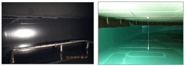
The common pigment used to manufacture conductive linings is graphite, which results in a dark color inside the tank (Figure 4). In contrast, the pigments used in non-conductive linings do not contain graphite, and therefore these linings are commercially available in brighter colors (Figure 5).
Light colored non-conductive linings are generally easier to inspect and clean. Furthermore, tanks with non-conductive linings can be inspected for the presence of holidays, pinholes and other defects using spark tests.
 Images: PPG
Figures 4 and 5: The view inside tanks coated with conductive (left) and non-conductive coatings.
Conductive linings do offer some benefits regarding static electricity because they conduct any static charge into the steel tank, they are not dependent on uncoated steel parts (e.g., pipes) to conduct the charge and they have a reduced risk of static electricity building up inside the tank. Of course, this is only true if the linings have a low enough electrical resistance in order to discharge or conduct any static electricity.
Are Conductive Linings Needed?
Although there are some countries with regulations on conductive linings, the majority of the global market does not have these requirements.
Based on different standards and procedures in the field, it can be concluded that proper grounding, the use of additives, quality construction of the tank and supporting infrastructure and adherence to safe operating procedures is sufficient provided that at least one of the three ingredients in the ignition triangle is eliminated.
The best practice design features are recommended regardless of whether the tank is uncoated, coated with a conductive lining or coated with a non-conductive lining. However, conductive linings can be used if desired as an additional safety measure to prevent a buildup of static electricity.