An ISO/ASTM-qualified two-part composite repair system is required to rectify defects in a wide range of equipment, including large-diameter pipelines, high-pressure piping, bends, flanges, valves, reducers, joints, valves, gaskets, fittings, pressurized vessels and tanks, saddles, main body connections, supports, nozzles and tees.
The new composite repair system utilizes two material components:
- A 100% solids epoxy-based resin that offers excellent mechanical properties, erosion/corrosion resistance and affordability.
- A hybrid carbon/glass reinforcement fiber sheet that provides mechanical strength and flexibility for better long-term thermal cycling performance.
Not only do such repairs rely on pre-qualified materials and pre-defined mathematical designs, but also on competent application craftsmanship.
Proper Validation Training for Installers
All personnel in charge of the execution, inspection and design of such repairs will be properly trained and validated by the composite repair manufacturer. The validation process is provided by some manufacturers in order to train and certify installers, supervisors and designers of composite repair systems.
Potential installers and supervisors will undertake initial validation in an off-job training environment, where they will receive theoretical and practical instructions in the installation and supervision of composite repair systems. Installers will complete a test piece repair that will then be inspected and destructively hydro-tested to ascertain quantitative data on that application performance. (Learn about destructive tests in general in the article 3 Essential Types of Material Destructive Tests.)
In addition, supervisors will attain full validation on a live application project after a prudent time agreed upon by the composite repair system manufacturer. Each installer is issued a certificate and identification card valid for a period of one year. Installers are expected to provide records of at least ten repairs in any one year after validation to wave recertification. Otherwise, installers will require a revalidation of their competency.
At least one repair system manufacturer also requires that potential designers will undertake training and validation in a training environment, where they will receive theoretical instructions on the design methodology for each defect type and geometry. Designers will be assessed by the composite repair system manufacturer. Installers, supervisors and designers will be issued a certificate and identification card by the composite repair system manufacturer.
Key Components of Composite Repair
As shown in the diagram below, three main roles are involved in bringing compliant composite repair work to fruition. Once the damage has been assessed by the client (end user), they contact the composite repair supplier. The composite repair supplier is often the validated application company that contacts an approved design company (designer), who will then submit a design data sheet to the client.

The design data sheet is the repository for all the information pertaining to each case of damaged equipment and will be completed by the client. Good communication between the end user and the designer is paramount in fully understanding the nature of the problem and possible repair scenarios. Information provided in the design data sheet will be used by the designer to initially confirm the type of repair based on the nature of the defect and the geometry of the repair.
Some of the data to be supplied by the end user and gathered by the designer include, but are not limited to the following:
- Original equipment design variables consisting of process design and operating conditions, mechanical loads and a detailed description of the damaged area. Any complementary information such as isometric drawings, pictures or schematics deemed necessary.
- Maintenance and operational history including documentation of any significant changes in service conditions, past repairs and any inspection reports detailing the nature of the area to be repaired.
- Service condition data including expected repair lifetime, required design and operating variables, expected future service conditions and required time scale for the application.
- End user facilities available during implementation of the repair.
Composite repairs can be designed for type A and B defects:
Once the type of defect and geometry of the repair are confirmed, the designer will calculate the repair parameters, thickness of the composite repair, axial extent of the repair and the number of required wraps.
The designer will contact the end user to formally authorize or reject the composite repair application. If application is authorized, the repair parameters should be shared with the end user.
The installer will carry out the application and, as discussed above, they will possess proper validation issued by the composite repair manufacturer.
Composite Repair Installation Methodology
Installation is relatively easy and can deliver a compliant repair to a damaged substrate. An example of a procedure for a compliant solution is detailed as follows:
- Prior to the application:
- The materials to be used will be in their right amounts and in good condition, and reinforcement materials will be free of contaminants or damage.
- The environmental conditions, dew point, ambient temperature and substrate temperature, will be monitored.
- The application area will be properly identified as per design.
- The surface to be repaired will be prepared as per NACE No. 2/SSPC-SP 10 “Near White Metal” and freed from contaminants as per SSPC-SP 1. Surface angular profile will be at least 3 mills (75 micron) confirmed by Testex® Replica Tape measurements as per NACE RP0287.
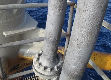
Surface prepared by blasting, and degreased with Belzona 9111.
- Application should commence as soon as the surface preparation activity has been completed. In the event that the substrate is suffering from metal loss, the original thickness of the substrate can be rebuilt by using compatible epoxy-grade paste materials prior to application of the composite system.
Pit filling with Belzona 1121.
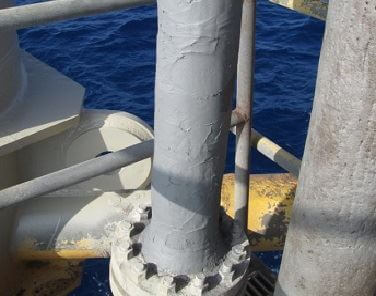
- Once the resin is selected, HD or LT, it is then applied onto the substrate. The resin should be pushed deep into the substrate profile to minimize the risk of air entrapment and in the process, achieve an optimum bond with the substrate. The glass fiber/carbon reinforcement sheet should then be wetted with the same resin.

Four wraps (8 layers) of Belzona 1982 applied.
- The wetted reinforcement sheet should be wrapped over the first layer of resin, maintaining a pre-fixed degree of overlapping throughout the axial extent of the repair. In order to achieve intimate contact between layers, firm hand pressure should be exerted in every wrap. The angle at which the reinforcement sheet is laid should be alternated in every wrap to make the fabric fibers as multidirectional as possible, hence ensuring that the repair is strong in all directions.

Belzona 9382 applied to consolidate repair during cure.
- The same procedure should be repeated until the required number of wraps has been achieved. Repair will be then consolidated by tightly wrapping a release plastic film, ensuring a high-quality laminate, with no air entrapment or voids.

Complete application of Belzona Superwrap II System.
- The system must be allowed to cure and only returned to service after full cure has been achieved.
As shown in this table, tangible evidence of proper application standards will be provided by the supervisor upon completion of the repair including, but not limited to the following details.
Table 1 – Application Documentation Package
In Summary
By using a qualified two-part composite repair system and validated, best-practice installation, supervision and design personnel, equipment can be safely rectified to a "zero-defect" status.
Read the first part of this series: Designing & Testing a New ISO/ASTM-Compliant Composite Repair Solution