Choosing an appropriate vessel lining system is a process that begins when asset owners are provided with demonstrable pre-qualification data on available linings and their capability to perform in the operating environment of their equipment. The oil and gas industry, like all business sectors, has developed material pre-qualification tests and set pass/fail values based upon their many decades of operational experience and recognition of both benefits and risks in selecting fit-for-service solutions.
Typical Industry Testing Requirements
Material pre-qualification requirements will vary from one asset owner or operator to another, but it is the opinion of the author that the following list provides the key fundamental international tests to be found in almost every client’s vessel lining testing specification:
- Adhesion
- Immersion Resistance
- Permeation Resistance
- Steam-Out Resistance
- Explosive Decompression
- Low Temperature Thermal Shock
- Chemical Resistance
- Abrasion/Erosion Resistance
Whenever possible, all the testing procedures should be aligned to internationally standardized methodologies such as those provided by ISO, NACE, and ASTM among others. The specific test conditions such as media, testing temperature and pressure, number of samples and dimensions, and laboratory certification shall be discussed between the client or design authority and the lining manufacturer.
Here we will discuss specifications 1 through 5 above, and then we will complete our discussion of the remaining types of international tests used for the selection of fitting lining systems based on specific sites and types of process service. (For a general overview, read Introduction to Managing Internal Corrosion in Process Vessels.)
Adhesion
Adhesion strength quantitatively characterizes the capability of a lining applied onto the rigid substrate of a vessel to withstand the loads or stresses exerted by the surrounding environment during both normal and upset conditions. The adhesive strength of a lining can be compromised by a variety of factors.
Rapid decompression, for instance, will cause any dissolved gas within the lining to expand faster than it can diffuse out of the lining. As a result, the lining at the bond line would be subjected to tensile forces. If such forces are greater than the adhesive strength of the lining, it will blister or prematurely fail. This is one of the reasons why a great number of asset owners include adhesion testing on a test panel as part of the vessel lining application process.
The adhesive strength of linings is commonly determined by dolly pull-off in accordance with ASTM D 4541.1 This test determines the greatest perpendicular force that a lining can bear before detaching.
The pull-off adhesion test employs these elements:
- A test fixture commonly referred to as a dolly
- An adhesive to bond the dolly to the lining
- The lining to be tested
- The substrate
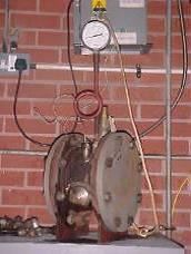
A class of apparatus known as portable pull-off tester (Figure 1) is used to pull the dolly in a perpendicular direction with respect to the substrate. Failure will occur either along the weakest plane within the lining itself, the adhesive, the adhesive/lining interface, the lining/substrate interface, or within the actual substrate, and will be evident by examination of the fracture surface.
Figure 1: Adhesion testing using one type of pull-off tester (Photo by D.T. Greenfield)

The lining is applied onto a suitably prepared metallic panel in accordance with the lining manufacturer’s instructions. Once the lining is allowed to cure, a dolly of fixed diameter is bonded to the lining using an appropriate adhesive. The dolly is then pulled until failure. The pull off force attained at failure is divided by the area of the dolly used and expressed in units of applied pressure, psi or MPa.
The pressure exerted at failure is an indicator of the adhesive strength of the lining, the greater the force, the greater the adhesive strength of the lining. Typically, there will be a minimum failure adhesion requirement specified as a pass or fail for the applied lining. For vessel linings this figure can vary from one asset owner to another, but at least one lining manufacturer reports epoxy based linings generating adhesion strength values in excess of 4,350 psi (30 MPa).
Immersion Resistance
The main purpose of a lining is to protect the carbon steel substrate by providing a barrier between the substrate and the surrounding environment. The immersion resistance of a lining is typically assessed via Atlas cell testing in accordance with NACE TM0174.2 This method is used to assess the maximum temperature at which a lining is able to offer adequate long-term protection when continuously immersed in liquid phase. Deionized water is most commonly used as test media because it has the greatest ability to permeate linings.
Two types of Atlas test cells are usually employed depending on the test temperature:
- Atmospheric pressure glass cells for testing of lining up to 203°F (95°C)
- Steel pressure cells for testing of linings at temperature levels above 212°F (100°C)
A typical glass cell test (Figure 2) consists of a three-neck glass tank cylinder equipped with various accessories such as thermocouples, bubblers, agitators and a cooling water condenser among others. A steel pressure cell (Figure 3) is based on the same principle as the glass cell test, but uses a sealed steel three-neck cylinder instead.
Figure 2: Glass Atlas cells in use under laboratory controlled conditions

Figure 3: Steel Atlas cell in use under laboratory conditions
If one-side testing is employed, only one side of the lined test panel is exposed to the chemical environment. In this case, two test panels can be simultaneously tested. The test panels are then bonded to the glass cylinder to create a sealed assembly that holds the liquid media.
The thermocouple is inserted into one of the necks of the glass cylinder to monitor the temperature of the liquid media. The liquid media can be heated by means of electrical heaters, electrical mantles, a steam-heated coil or any other external heating method. The second neck is commonly used to fit a cooling water condenser to maintain a constant level and concentration of the test solution during testing. The third neck can be used to fit an agitator, if required, or sealed if unused.
Figure 4: Schematics of a glass Atlas cell showing assembly of testing plates

One-side testing is usually preferred by asset owners because it approximates the cold-wall effect (also known as cold-wall blistering) found in service conditions when a significant thermal differential between the lined surface of the vessel and the vessel outer skin is observed. The temperature gradient accelerates the rate of water permeation through the lining towards the cooler substrate, promoting blistering or delamination.3
The lining is applied onto suitable prepared test panels and bonded to the glass tank cylinder. The cell is filled two-thirds with the test media. This allows for two distinct exposure phases to be created:
- A fully immersed phase where the lining will be exposed to the liquid media
- A vapor phase where the lining will be in continuous contact with vapors
Commonly, the lining is examined after the first, third and sixth month of exposure to the test environment for any visual change of color, gloss or smoothness. It is also inspected for signs of failure such as blistering, cracking, delamination and rusting among others, and properly evaluated in accordance with ASTM D7144, ASTM D6105, and ASTM D 45411. If the lining is intact with no signs of failure, the product can be recommended for long-term immersion at the test temperature.
Permeation Resistance
Linings must be able to resist permeation by gases or liquids as much as possible during service. Otherwise they will not be capable of providing long-term protection to the substrate. Should gases and liquids be able to freely permeate the lining, they will find their way through the lining until reaching the lining/substrate interface.
At this point, the lining is no longer acting as a barrier between the chemical environment and the substrate; hence an ideal environment for corrosion to occur is created. As the metallic substrate oxidizes, oxidation products occupy a greater volume than that of the steel from which they came from, exerting additional pressure on the lining at the bond line. If severe enough, this pressure can overcome the adhesive strength of the lining.
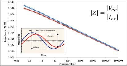
Electrochemical impedance spectroscopy (EIS) is a powerful and non-destructive laboratory technique that can be used to investigate the deterioration of a lining due to exposure to the environment (Figure 5). EIS achieves this by quantitatively measuring the resistance or impedance of such a lining to the flow of current through it.
Figure 5: EIS equipment

This technique is fast becoming an accepted industry measure of lining performance as it can determine the level of water penetration into the lining and associated blister formation, lining swelling and loss of adhesion including delamination.6 The more permeated a lining, the lower its resistance to the flow of current.
Figure 6: EIS scan profile
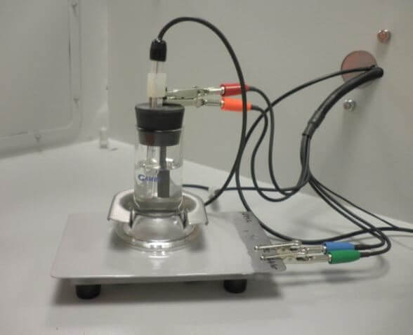
In order to carry out the EIS analysis in accordance with ISO 167737, a coated metallic sample is placed in a Faraday cage to isolate it from external interference and a standard three-electrode cell is created.
The coated sample serves as the working electrode, onto which a glass cell is clamped, isolating a fixed 2 in2 (12.57 cm2) area of lining. The circuit is completed with a graphite counter electrode, standard Calomel reference electrode (SCE), and a 1% potassium chloride electrolyte (Figure 7). The system is then attached to a potentiostat, which will measure the magnitude of the impedance at a specific range of frequencies.
Figure 7: Electrochemical cell for coating analysis
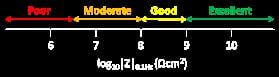
The logarithm of the impedance absolute value at 0.1 Hz, log10|Z| is typically used to gauge the level of protection offered by the tested lining. A value below 6.5 is indicative of poor protection. Values in the range 6.5 to 8 indicate the lining offers moderate protection. Values between 8 and 9 show that the barrier properties of the lining are good, and values greater than 9 demonstrate that the lining offers an excellent level of protection (Figure 8).
Figure 8: log10|Z|0.1Hz scale for lining protection
In actuality, EIS measurements are not absolute. They must be used comparatively because a single EIS spectrum offers little information on the level of protection offered by the lining. This is the reason why this technique is usually employed in conjunction with Atlas cell testing.
By comparing the logarithm of the impedance of a lining before and after it is tested in an Atlas cell for 6 months, it can be determined whether the lining is able to offer a poor, good or excellent level of protection. Hence, a high performance lining should generate log10|Z| values in excess of 10 before and after being subjected to test regimes.
Steam-Out Resistance
Typically, process vessels are thoroughly cleaned prior to opening for maintenance and inspection. Vessels in the oil and gas industry are no exception. They need to be cleaned out to remove residual oils, chemicals, and other contaminants prior to conducting an inspection on the vessel substrate or existing lining, in the case of lined vessels. (Learn more about cleaning and Substrate Surface Preparation for Corrosion Prevention.)
The cleaning process can be carried out by using chemicals or pressurized steam. The latter is commonly referred to as steam-out process. Steam-out is a purging process that employs pressurized steam at temperature levels close to or above 390°F (200°C) for as long as 24 hours.
Steam is used conveniently and efficiently for this purpose for various reasons:
- Steam’s caloric content helps to break down viscous residues.
- Steam has no combustible oxidant.
- Condensed water facilitates flushing and rinsing of the vessel contents.
As a result, any vessel lining used must be resistant to high temperature steam.
To assess the suitability of linings for such applications, coated samples should be exposed to high-temperature steam for a suitable period. Several asset owners require the lined specimens to be exposed to steam for at least 21 days. After that time, the specimens are inspected for any signs of failure/damage as a result of the high temperature exposure.
A lining can only be recommended for steam cleaning up to the temperature at which no significant damage is observed. Advanced epoxy linings are tested to 410°F (210°C) demonstrating the capability of epoxy linings to resist short-term excursions to temperature levels above those normally recommended for service under immersion.
Explosive Decompression
As previously discussed, in pressure vessels where gases and liquids are stored at higher than atmospheric pressure levels, there is the tendency for any fluid or gas within the system to permeate the lining to a certain extent. In order to assess the ability of a lining to resist the effects of decompression, controlled testing can be carried out in accordance with NACE TM0185.8
The apparatus employed for this test is an autoclave. The test medium normally used for evaluating explosive decompression resilience of linings in the oil and gas industry consists of three phases – hydrocarbon, water and gas:
- As the hydrocarbon constituents in crude oil are very dependable sources of crude oil, the hydrocarbon phase used for explosive decompression testing is usually a 50:50 (v/v) mixture of kerosene and toluene.
- The water phase is commonly seawater.
- The gas phase can have multiple components depending on requirements set forth by the asset owner or operator. However, most tests are conducted using a gas mixture of methane, nitrogen, carbon dioxide, and hydrogen sulfide in different concentrations.
Coated panels are sealed in the autoclave and exposed to the test media environment at elevated temperature and pressure levels as dictated by the specific target application. Following a predesignated time period (enough to allow for reliable evaluation of the lining integrity), usually from 21 to 28 days, the autoclave is decompressed at a previously determined rate within 15 to 30 minutes.
The rate of decompression is particularly critical to the stresses placed upon the tested lining materials and also to the success rate. At least one lining manufacturer uses decompression rates from 1,450 psi (100 bar) to 725 psi (50 bar) in 5 minutes and from 725 psi (50 bar) to 0 psi (0 bar) in 10 minutes for explosive decompression testing protocols.
The panels are removed from the autoclave and allowed to cool to ambient temperature prior to inspecting the lining’s integrity. The lining must be inspected in both gaseous and liquid phases in comparison to an untested specimen to determine any signs of failure such as blistering, color change, softening, underfilm creep and disbondment among others. If no failure is observed, it can be concluded that the lining is resistant to decompression from the elevated conditions to ambient temperature at the tested decompression rate.
References
- ASTM D4541-09e1, “Standard Test Method for Pull-Off Strength of Coatings Using Portable Adhesion Testers” (West Conshohocken, PA: ASTM International).
- NACE TM0174-02, “Laboratory Methods for the Evaluation of Protective and Lining Materials on Metallic Substrates in Immersion Service” (Houston, TX: NACE).
- J.R. Kosek, J.N. Dupont, and A.R. Marder, “Effect of Porosity on Resistance of Epoxy Coatings to Cold-Wall Blistering”, Corrosion Science Vol. 51. No. 11 (1995).
- ASTM D714-02(2009), “Standard Test Method for Evaluating Degree of Blistering of Paints” (West Conshohocken, PA: ASTM International).
- ASTM D610-08(2012), “Standard Practice for Evaluating Degree of Rusting on Painted Steel Surfaces” (West Conshohocken, PA: ASTM International).
- Hinton, J. Andrew, “Determination of Coating Adhesion Using Electrochemical Impedance Spectroscopy.” Solartron, Materials Test, Farnborough, Hampshire, UK.
- ISO 16773-2:2007, “Electrochemical impedance spectroscopy (EIS) on high-impedance coated specimens Parts 1, 2 and 3 (Geneva, Switzerland: ISO).
- NACE TM0185-2006, “Evaluation of Internal Plastic Coatings for Corrosion Control of Tubular Goods by Autoclave Testing” (Houston, TX: NACE International).