Dissolved Air Flotation (DAF) Tanks are used to clarify waste waters by removing suspended solids, oils and other contaminants. A pressurized stream of air saturated, clarified water is mixed with the sewage effluent in the DAF separation chamber. With the release of pressure dissolved air comes out of the solution producing a cloud of microscopic bubbles. These bubbles attach to the solids, floating them to the surface to be mechanically skimmed and removed from the tank. The clarified effluent overflows from the DAF tank via an over/under weir to the next stage of treatment.
DAF tanks are exposed to varying temperature, pH and hydrogen sulfide (H2S) levels. Corrosion protection is generally provided by application of a suitable coating and selecting corrosion resistant materials for various components. (Get an introduction to this topic in the article Corrosion Costs & Recommended Practices for the Water Industry.) DAF tanks are periodically drained and cleaned to prevent sludge build up and to undertake repair/maintenance works.
Galvanic Cathodic Protection for a Sewage Treatment Tank
A Water Authority recently took off-line their DAF tank located at its Sewage Treatment Plant for five-yearly cleaning and maintenance. Upon inspection, extensive corrosion was observed inside the tank, requiring recoating of the entire tank and upgrade of several components. The Water Authority contacted Freyssinet for discussion on the possibility of installing a cathodic protection system to minimize the internal corrosion, extend the life of the new coating system, and lengthen the time between planned shutdowns. (Cathodic protection systems are discussed The Basics of Cathodic Protection.)
Following site investigations and a review of tank drawings, a decision was made to install a galvanic anode cathodic protection system to provide protection to the internal wetted steel surfaces of the DAF Tank.
The galvanic anode cathodic protection system was preferred over an impressed current system for the following reasons:
- To simplify installation and minimize maintenance.
- To eliminate the need to supply DC electrical power.
Magnesium alloy anodes were selected to limit the number of anodes required to achieve maximum protection in the given environment inside the DAF Tank. In order to ensure uniform protection of all immersed elements of the tank including the moving parts, raking arms and so on, the entire surface area to be protected was categorized into various components and suitable anodes were selected to provide protection to these components. In total, thirty nine (39) magnesium anodes of four different styles were selected to provide protection to all components including floor and walls, internal and external areas of the central drum, the skimmer box frame, run-off water trough, influent pipe and rotating arms.
Coatings for a Sewage Treatment System
A paint coating system, consisting of Jotaprime 505 epoxy primer with a second and third coat of Jotacote 605 high solids epoxy, was applied to the tank surface with a minimum total dry film thickness (DFT) of 350 microns.
The system was designed with a minimum design life of 5 years, equivalent to the period between maintenance shut-downs with potential to replace anodes at this time.
Design of the Galvanic Cathodic Protection System
The design of the cathodic protection system was undertaken in accordance with the following Standards:
- AS 2832.4 Guide to Cathodic Protection of Metals, Part 4: Internal surfaces
- AS 2239 Galvanic (sacrificial) anodes for cathodic protection
- AS 1554.1 Welding of Steel Structures
The design included the fixing of anodes using mild steel studs welded to the tank at selected locations. The anodes were secured with nuts, flat and spring washers. The bolted connections were selected to facilitate easy replacement of consumed anodes during future shutdown periods. The bare anode straps and bolted connections were coated with a bituminous coating to reduce the amount of exposed steel to be protected. The anodes on the tank wall and influent pipe were installed with an offset from the wall and the pipe. At all other locations anodes were flush mounted using an insulating gasket to prevent direct contact between the anode body and the tank.
The anode manufacture, dimensions, tolerance, testing and supply was in accordance with AS 2239-2003, and were cast to Magnesium Alloy designation M3 (low potential grade).
As several of the components installed within the DAF Tank were fabricated from stainless steel, including a new skimmer box, these were isolated from the carbon steel tank metalwork using suitable insulating materials including bolt isolation sleeves and washers.
The protection criteria used for the design and commissioning of the system is as per AS 2832.4, Cathodic Protection of Metals, Part 4: Internal surfaces, which states that the potential at all surfaces should be equal to or more negative than -0.850 volts with respect to a copper / copper sulfate reference electrode.
The Standard states that accurate potentials, i.e. free of voltage gradients effect, can be obtained using the “structure off" method of potential measurement. For a galvanic anode system it is impractical to measure “Off” potentials. For this structure, CP “On” method of potential measurement was used to confirm the achievement of full protection. Due to the low resistivity of sewage and even distribution of the anodes, the voltage gradients were expected to be minimal.
Evaluating the Effectiveness of the System
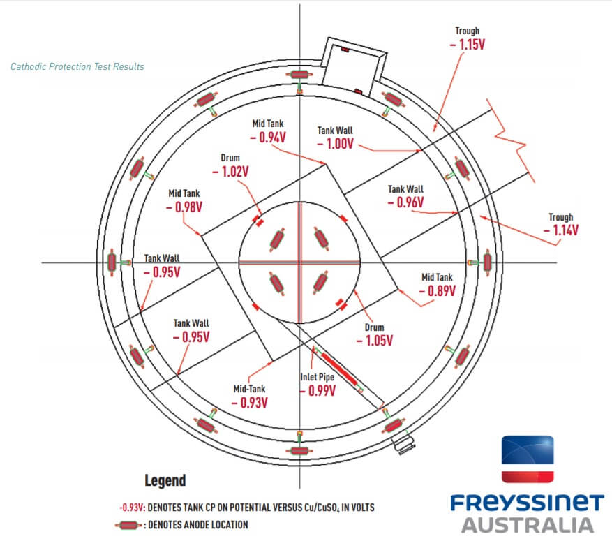
Evaluation of the cathodic protection system was undertaken after the DAF Tank was placed back on-line with effluent being processed. The CP “On” potentials of the DAF Tank were measured at different locations against a portable copper / copper sulfate (Cu/CuSO4) reference electrode using a high input impedance voltmeter. The results are shown in the diagram below.

Test results indicate that the cathodic protection system is operating satisfactorily with CP “ON” potentials at all locations being equal to or more negative than -0.85 volts versus a copper/copper sulfate reference electrode. Further evaluation of the system will be undertaken during the next maintenance shut down.