Cathodic protection potential measurement is a method used to determine the adequacy of a cathodic protection (CP) system—applied to protect a certain structure—by comparing the measured potential with certain criteria. (Get up to speed on cathodic protection systems by reading The Basics of Cathodic Protection.) For adequate measurement, you have to ensure proper selection and installation of equipment used in field measurements.
One should consider some situations where the potential of buried pipelines can't be measured effectively, such as elevated temperatures, disbonded or thermally insulating coatings, shielding, bacterial attack and unusual contaminants in the electrolyte.
Below we will talk about some of the concerns that ofen come up during cathodic protection potential measurements.
Instrument Selection and Proper Use
There are many factors that influence the selection of instruments used for field measurements:
- Input impedance of digital voltmeter or input resistance for analog voltmeter. In order to eliminate measurement errors, the input impedance must be several orders of magnitude higher than the total resistance of the measuring circuit.
- Sensitivity. The capability of the instrument to detect a small unit of a given parameter when used under reasonable conditions.
- Accuracy. The amount of uncertainty in a given measurement because a reading from a digital multimeter can differ from the actual input. Accuracy is often expressed as: (% Reading) + (% Range). The accuracy is to be checked by comparing the reading to another acceptable voltage source or to another appropriate instrument known to be accurate.
- Instrument Resolution. The smallest change in an input signal that produces, on average, a change in the output signal. Resolution can be expressed in terms of bits, digits or absolute units, which can be related to each other.
- Ruggedness. The instrument to be manufactured from a material that withstands the operating environment.
- AC and Radio Frequency (RF) signal rejection. Noise in a measurement can originate from the instrument taking the measurement or an interfering signal passing through the instrument and causing measurement instability. Errors due to noise are common in areas near HVAC transmission lines.
- Temperature and other climatic limitations. The instrument operating parameters are influenced by temperature and climatic limitations.
For proper usage of instruments, the user should know the capabilities and limitations of the instrument by following the manufacturer's instructions.
Half-Cell Selection, Calibration and Maintenance
The half cell is a stable reference electrode used to measure the potential of another electrode. There are several types of reference electrodes, but the most common types are saturated copper/copper sulfate (CSE) electrode, silver/silver chloride (SSC) electrode, and saturated calomel electrode (SCE).
Half-Cell Selection
The selection of a reference electrode depends on the application's environment:
- CSE is usually used in soil and freshwater environments
- SSC is usually used in seawater environments
- SCE is usually used for laboratory work
Half-Cell Calibration
This can be done by measuring the voltage difference between the used reference and another standard (unused) reference, as shown below.

If the voltage difference between the two reference electrodes is more than 5 mv, maintenance is required for the field reference electrode.
Half-Cell Maintenance
Proper maintenance consists of the following steps.
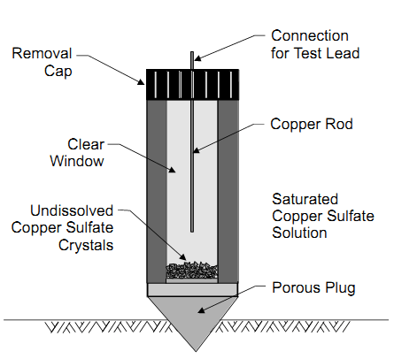
- The copper rod may be cleaned with a 10% nitric acid solution and the rod should be immersed for several minutes to remove all surface products and contaminants. Sandpaper may be used for cleaning the copper rod.
- After cleaning the rod, it should be thoroughly rinsed in distilled water.
- The plastic electrode tube can be washed with soap and water rinsed with distilled water.
- The porous ceramic plug may be soaked in distilled water to reduce or eliminate any contaminants.
- Soaking for several hours may be required, with several changes of the water.
- When the electrode has been fully cleaned, it can be re-assembled and filled with the copper sulfate solution.
- The copper sulfate solution should be saturated, with loose crystals visible, and the end cap placed over the plug when not in use (to prevent leakage and contamination).
Field Connections
Field connections are used when measuring the potential of the buried pipeline with respect to a stable reference electrode. For accurate measurements, the reference electrode needs to be placed directly over the center line of the pipe.

The pipeline needs to be connected to the voltmeter's negative terminal and the reference electrode to the positive terminal. With this connection, the current will flow from the voltmeter positive terminal to the negative terminal.
The displayed value is positive, indicating that the reference electrode is more positive than the pipeline. The electrical continuity of the pipeline needs to be checked before the measurement.
Considerations During Measurements
During pipe-to-electrolyte potential measurements, which determine the level of cathodic protection at the test site, one should consider the following:
- Effectiveness of coatings, particularly those known or suspected to be deteriorated or damaged
- Bare sections of pipe
- Bonds to mitigate interference
- Parallel coated pipelines, electrically connected and polarized to different potentials
- Shielding
- Effects of other structures on the measurements
- History of corrosion leaks and repairs
- Location of impressed current anodes
- Unknown, inaccessible or direct-connected galvanic anodes
- Location of isolation devices, including high-resistance pipe connections and compression couplings
- Presence of electrolytes, such as unusual corrosives, chemical spills, extreme soil resistivity changes, acidic waters and contamination from sewer spills
- Location of shorted or isolated casings
- DC interference currents, such as HVDC, telluric, welding equipment, foreign rectifier, mining equipment, and electric railway or transit systems (Read Stray Current Corrosion and Preventive Measures for more on these sources.)
- Contacts with other metals or structures
- Locations where the pipe enters and leaves the electrolyte
- Areas of construction activity during the pipeline history
- Valves and other appurtenances
- HVAC overhead power lines
Voltage Drop Errors
According to Ohm's Law:
V = IR
where
I: represents the cathodic protection current
V: represents the total voltage drop
R: represents the path resistance
Voltage drops, rather than those across pipe/electrolyte interfaces, represent an error due to the passage of current in the voltmeter, test leads, reference electrode, electrolyte, coating and the pipe itself.
Elimination of Voltage Drop Errors
In order to eliminate errors in the measured potential, the following needs to be considered:
- The input impedance of the voltmeter needs to be higher than the total measurement circuit resistance. Input impedance of 10 Ohm is sufficient for accurate measurement, while lower values may be accepted if they're higher than the total circuit resistance.
Note: The difference between errors can be due to the design accuracy of the voltmeter and due to voltage drop errors in the measuring circuit.
- The contact resistance of the reference electrode needs to be as low as possible. This can be done by wetting the contact area, especially for frozen, concrete or asphalt layers.
- Test leads need to be checked for any broken points, bare areas or bad connections.
- For accurate measurements, it must be taken in the upper two-thirds of the selected range for a particular instrument.
In order to eliminate voltage drop errors due to the passage of current in the electrolyte, one of the following must be considered:
- The reference electrode should be placed very close to the buried pipeline, maybe at a distance twice the reference electrode diameter.
- Interruption of CP current sources instantaneously in order to measure the polarized potential of the pipeline. CP current sources includes impressed currents, galvanic anodes, stray currents and electrical bonds.
Note: Before current interruption, a time for polarization needs to be considered.
Voltage drop errors due to the passage of current in the pipe itself needs to be considered, especially when the reference electrode is placed remotely from the pipeline connection. These errors either cause an increase or decrease in the measured potential according to the direction of current with respect to the reference electrode position. These errors commonly appear when close interval potential surveys are conducted. (For more on this topic, read The Benefits of Timely and Effective Reporting When Conducting Pipeline Close Interval Surveys.)
Conclusion
Potential measurement is an important method used for several cathodic protection surveys. It has to be done by a qualified person for accurate measurement records.