The pipeline industry is very collaborative in terms of cathodic protection, as everyone’s protection systems can affect each other’s assets detrimentally and end up inadvertently causing corrosion due to stray currents. (This topic is explored in detail in the article Stray Current Corrosion and Preventive Measures.)
Case Study of a Cathodic Protection System
When a water authority wanted to increase the current output of their protection system, there was an increased risk of interfering with other asset owners in the area, so they contacted the gas authority for that area. There had already been issues with interference with the original commissioning of this system on the gas main and hence a bond (connector) exists from being previously installed to make the water and the gas mains electrically continuous to mitigate this previous interference.
Collaborative investigations into what the consequences of increasing the water systems’ current output to 10 amps would be found that the gas pipeline drained almost all of the additional protection current through the aforementioned bond. The protection levels on the gas pipeline, however, remained fairly unchanged and unprotected to the -850 mV criterion in AS2832.1:2015. The 10 amps of current flowing to the gas main would be expected to have improved potentials quite substantially, especially close to where the current was being picked up from the water pipeline. However this was not the case. Why? The suspicion was formed that there was an electrical fault along the gas pipeline that was earthing any current being supplied to the gas main from the water main to earth and was hence not protecting either the gas or water main as intended.
Root Cause Analysis
The root cause of the problem was determined by conducting a coiling survey. (Discover how to optimize survey results in The Benefits of Timely and Effective Reporting When Conducting Pipeline Close Interval Surveys.) This type of survey consists of a signal being applied to the pipeline in question and an experienced technician tracing this signal along the pipeline path. Any attenuation in the signal or deviation from the expected path can indicate a fault. In this case the signal diverted from the expected path of the gas pipeline and was found to follow a copper fire service to a motel. This indicated that the suspected fault had been found and that the problem was the gas main and the fire service pipeline were touching underground and hence earthing all of the protective current from the gas pipeline and, by the same token, the bonded water pipeline.
Implementing a Solution to Isolate the Pipes
To confirm and rectify this issue the fault area was excavated, which showed that the fire service and the gas main were touching (see article's main image, above). The gas main was uncovered and shown to have a very good coating, with the only exception being around where the copper pipe was touching, where the coating appeared to have been damaged during its construction.
At this point the pipes were pried apart with wooden wedges to separate them from each other. It was found that the copper service had a small hole in it that was weeping water at the area of contact between the gas and the copper pipeline. Since this pipe was a fire service the damage had to be repaired within 2 days to ensure the integrity of the emergency system in case of a fire. The decision was made that the best way to simultaneously fix the fire service, separate the pipes and also give enough clearance to repair the coating on the gas main would be to reroute the copper fire service with 45-degree bends around the gas main. The gas main was wrapped with a standard Denso insulation tape and then a polyvinyl chloride (PVC) plastic tape as shown in Figure 1.
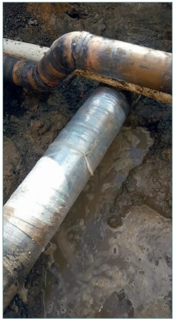
Figure 1. Copper fire main rerouted through a series of 45 degree bends and the insulation repair to the gas main.
During these isolation works the voltage potential of the gas main was being charted with respect to a calibrated typical copper/copper-sulfate reference cell. These recorded potentials revealed that at the time the fault was removed, at 11:02 am, potentials improved instantaneously and the pipeline went from about -750 mV to -1150 mV and was classified as being protected to AS2832.1 at this location all because of the fault rectification. These results are shown below.
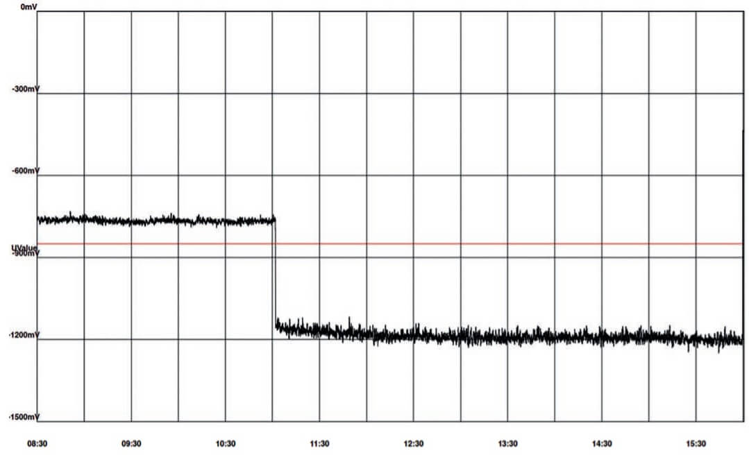
Figure 2. Graph of potential vs. time during the time of fault rectification.
This not only had good results for the gas pipework, ensuring that their asset was protected from corrosion and that the service life of the pipeline was extended, but the water authority has had the flexibility to increase protection and hence asset life through corrosion prevention too. An all-round good solution!