Pipelines have been used as a safe and cost effective method of hydrocarbon transportation since 1860. A routine inspection is required to ensure that the pipelines are able to transport the required hydrocarbons at the designed maximum operating pressure (MOP) while maintaining safety and integrity. The routine inspection can include pressure testing, pipeline pigging and other procedures.
Although pipeline pigging is thought to be a very effective method of inspecting the pipelines and determining the size and location of anomalies, some pipelines are considered non-piggable. This could be because they are located in hard-to-reach areas where launching and receiving the pig is difficult or the pipeline segment being inspected is part of a piping network where pigging will be extremely difficult.
Since 1998 pipeline operators began inspecting hard to reach pipelines or non-piggable pipelines with a technique known as guided wave ultrasonic testing (GWUT). This technique has the ability to detect and measure the change in the pipeline’s cross section from a single test location. This provides pipeline owners and operators with a way to monitor the pipeline's wall loss over time and provide them with economical and efficient decisions regarding their integrity programs. In this article we will explain the principle behind GWUT inspection, how it operates, its advantages, and its limitations.
What is a Guided Wave Ultrasonic Testing (GWUT) Inspection?
GWUT inspection is a technique developed in the 1990s to screen lengths of pipelines from a single test location that allows for full coverage of the pipeline. (For information on another inspection alternative, read Using 3D Laser Analysis for Nondestructive Testing and Evaluation of Pipeline Corrosion.) The results of the screening process are then inspected in more detail using conventional nondestructive testing (NDT) methods.
With GWUT inspection the access costs are reduced significantly; instead of excavating large lengths of pipelines for inspection, we can only inspect areas that were found corroded from the screening method. These areas are then thoroughly inspected using conventional NDT methods. Additionally, GWUT can be used to inspect hard-to-reach areas such as railway or river crossings that are difficult with conventional NDT methods.
GWUT Theory of Operation
GWUT is composed of a ring of piezoelectric and magnetostrictive transducers that are coupled around the entire circumference of the pipeline. These transducers generate and receive low frequency ultrasonic waves that are capable of travelling through the pipeline wall. The low frequency waves (usually in the 50 KHz range, which is much less than the 5 MHz range usually used in conventional UT inspection) are capable of travelling through the pipeline wall with minimum attenuation.
The GWUT transducers don’t require a couplant to be placed between the transducers and the pipe surface – only pneumatic pressure is maintained to achieve an intimate contact between the pipe surface and the transducers. Any change in the pipeline cross section causes a reflection of these waves back to the transducer where they are processed using computer software to estimate the change in wall thickness – either an increase due to welds or a decrease due to metal loss. Because the propagation speed of these waves is known, based on the time of flight of the ultrasonic waves the approximate location is calculated and determined (Figure 1).
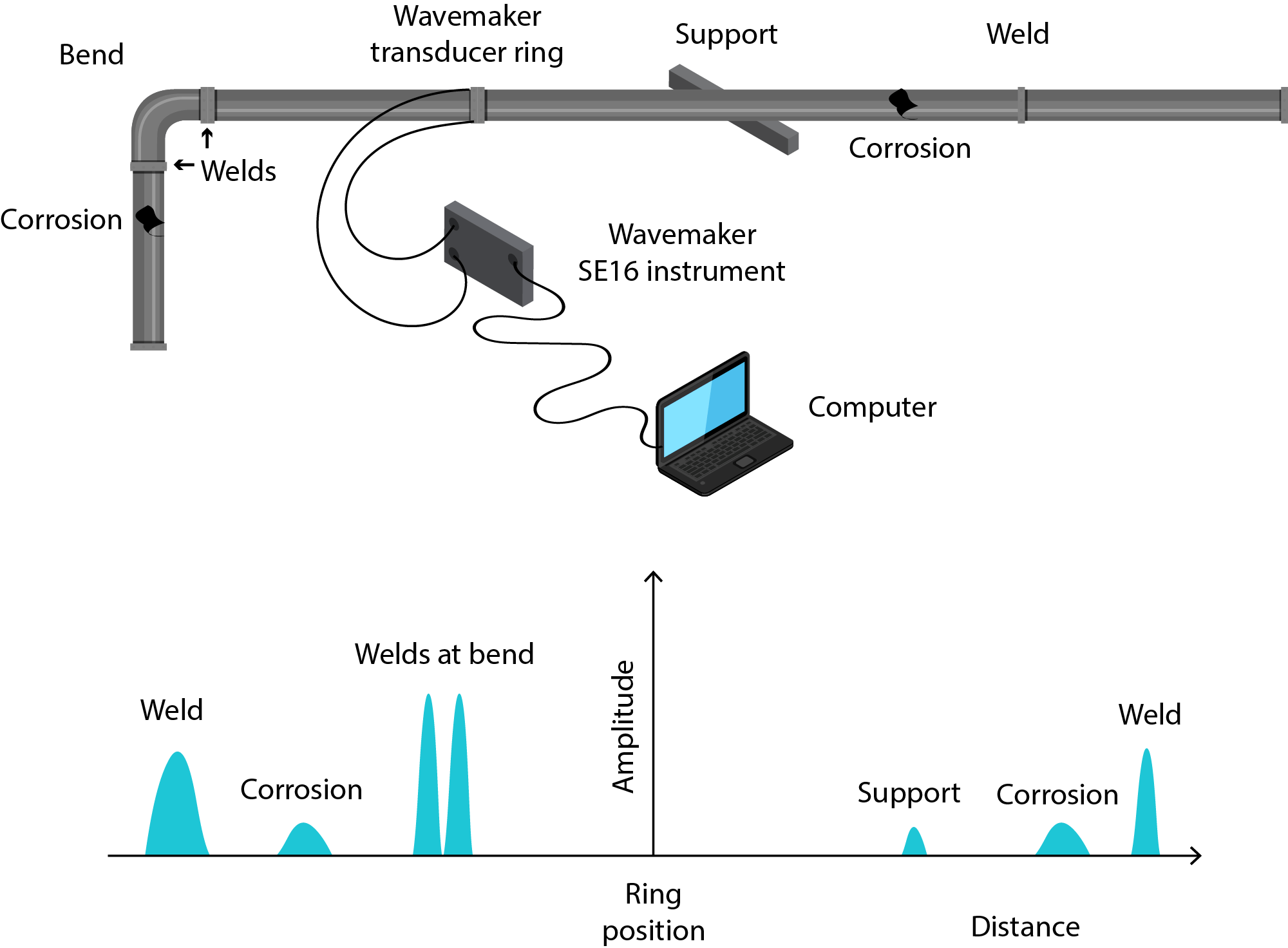
Figure 1. A representative diagram for GWUT inspection tool setup.
GWUT versus Conventional Ultrasonic Testing
Although GWUT uses the same principles as the conventional ultrasonic testing (UT) that is used to measure the pipe wall thickness or to detect cracks if an angled probe is used, GWUT has several advantages (Table 1).
|
Characteristic
|
Standard UT
|
GWUT
|
|
Frequency
|
High
|
Low
|
|
Wave mode
|
Compression/shear
|
Guided
|
|
Detection characteristic
|
Time of flight
|
Time of flight, wavemode, amplitude, pattern, response to frequency changes
|
|
Propagation mode
|
Pulse–echo
|
Pulse–echo
|
|
Measurement type
|
Point to point
|
Screening
|
|
Measurement
|
Change in thickness
|
Change in cross section area
|
|
Area of inspection
|
Beneath transducer
|
Not beneath transducer, many feet each side of transducer collar including buried sections
|
|
Needs couplant between transducer and pipe surface
|
Yes
|
Not needed
|
|
Relative accuracy in measuring wall thickness
|
High
|
Estimates wall loss in some test stations. Limited, not usually applicable in buried pipelines.
|
|
Relative examination area
|
Small
|
Large
|
Table 1. Comparing conventional (standard) ultrasonic testing (UT) with guided wave ultrasonic testing (GWUT). Source: NACE SP0313-2013 Guided wave technology for piping application.
Limitations of GWUT
Although GWUT is a viable solution for pipelines that are hard to inspect with conventional NDT techniques either due to access difficulty or due to complexity (e.g., a piping network), it has some limitations, as described below.
GWUT relies on mechanical waves that are induced into the pipelines through the transducers. These waves usually travel through the pipeline’s wall at a much lower frequency than conventional UT. The longer wavelengths with which the waves travel result in more complex signals than those produced from compression waves in conventional UT.
In GWUT, the waves exist in three modes: longitudinal, torsional and flexural. More than one mode could be available at the pipe under inspection at one frequency. This can lead to a response that is much more difficult to analyze than conventional UT. Therefore sophisticated software programs are required to analyze the signals. Also, the GWUT operators must be experienced and well trained in setting up and operating the equipment as well as analyzing the results produced.
As previously mentioned, GWUT is a screening method. It only measures the change in cross sectional area. It lacks the capability of accurately determining the depth and length of the metal loss area, which is a requirement to assess the pipeline carrying capability according to international standards as ASME B31G. Therefore GWUT is only a screening method and any areas reported as having a cross sectional change should be further assessed using conventional NDT techniques such as conventional UT. Figure 2 shows how a 10% cross sectional area flaw reported by a GWUT inspection was found to be a 10%, 20% or 40% depth depending upon the circumference of the metal loss. [3]
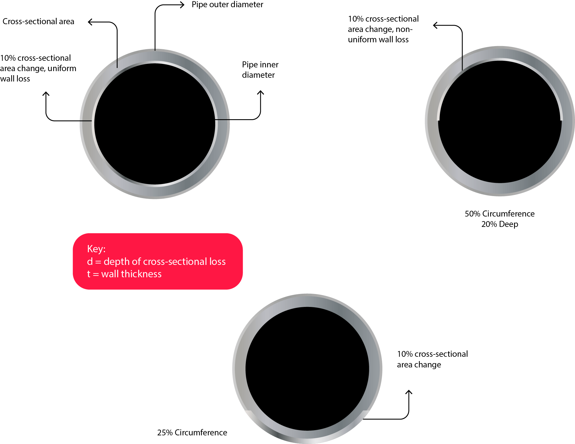
Figure 2. Examples of 10% cross section area flaw, and how different depths were reported.
Data calibration still relies on dynamic attenuation curves (DAC) where the primary curves relies on the response received from pipeline girth welds. These weld profiles are usually inconsistent due to any of several reasons including lack of penetration, improper alignment or a change in the cap or root of a weld. This can cause errors in the DAC curve that can’t be corrected without knowing the girth weld profiles up and down the pipeline. Moreover, the presence of two or more clusters of defects that are close together can affect the shape of the received signals, either by constructive or destructive interference. All these parameters affect the precision of the reported cross sectional area loss from GWUT inspection.
One of the main advantages of GWUT inspection is its ability to inspect large lengths of pipelines from a single test location. However, this is only applicable in ideal conditions. Other factors are can hamper the inspected length, including:
- The presence of pipeline coatings such as wraps, coal tar epoxies, concrete, etc.
- Degraded pipeline wall conditions due to the presence of pitting corrosion
- Complexity of the pipe geometry
- Viscosity of the pipe’s contents (as viscosity increases the inspected distance decreases)
- The pipeline’s depth, especially in dense and wet soil. Depending upon the field conditions, the length of the inspected pipeline section could be reduced to tens of feet, which might make the GWUT inspection cost ineffective.
The corrosion profile (depth, length) can’t be accurately determined.
Calibrating the data relies on field girth welds, which might have different profiles.
Finally, it must also be taken into consideration that there exists a dead zone beneath the GWUT transducers and a near zone beside the dead zone. In these areas the probability of anomaly detection is largely reduced. This must be taken into account when choosing the placement location for the GWUT transducers to be further away from the required section to be inspected.
Conclusion:
GWUT inspection is a very powerful tool that can be used to inspect pipelines that are difficult to access or un-piggable. (Other tools are discussed in Use of Non-intrusive Inspection in Onshore Gas Facilities.) This technique allows the pipeline operator to assess several hundreds of feet of pipeline from a single test location. However GWUT has some limitations that must be considered.
Keeping in mind its capabilities and limitation, it can provide an alternative inspection technique that aims to ensure the integrity and safe operation of the pipeline.