The CBH Group is one of Australia’s leading grain organizations, a cooperative with operations including grain storage, handling and transport, to marketing shipping and processing, based in Western Australia. It has been established for 80 years and is owned and controlled by more than 4500 grain growers.
The CBH Geraldton base is located in the north of the state’s growing region and consists of receival and administration facilities, along with port terminals for export. As part of this receival facility, Geraldton has twenty-four (24No) reinforced concrete grain silos which were constructed from slip formed concrete in the mid 1960s. These silos were constructed as circular grouped silos in a bank of 8 x 3 No. interconnected/adjoining silos, each 36 meters in height and 13 meters in diameter, resulting in a plan layout of 100 meters long and approximately 40 meters wide. This layout formed internal star cells between the main silos which are used to store boutique grain. The walls of the silos are around 200 mm (7.9 inches) thick and the wall reinforcement consists only of a centrally placed single mat.
In more recent years evidence of extensive vertical cracking was noted throughout the walls of these silos and this lead to various investigations and structural assessments. As is typically found for circular grain storage facilities of this type and age, it was concluded that the original design understanding was inadequate to cater for the peak loads occurring during grain outflow. (Related reading: The Root Causes of Today's Multifactorial Concrete Problems.) The resulting structural cracking reflected this structural inadequacy, and given the marine environment in which the silos are located, also raised concern in regard to the long-term durability of this structure.
Insufficient hoop reinforcement in the silo walls had resulted in extensive vertical cracking and led to restriction in grain loading and operation. As the silos are also located in a temperate marine location, 40 years of chloride ingress had also led to significant corrosion to the embedded reinforcement resulting in widespread delamination and spalling. (Learn more about these symptoms in the article Why Concrete Delamination Occurs – and What to Do About It.)
Project Summary
Following on from failed attempts at remediation during the early 2000s by others, Freyssinet were invited to put forward solutions for strengthening and remediation as a result of successful completion of numerous similar projects throughout Europe and the Middle East. This approach was largely one of providing a complete design and construct solution.
Previous structural assessment reports were assessed, and further grain testing and load modelling was undertaken by recognized specialist organizations. Freyssinet then completed a full in-house structural design for strengthening which included sophisticated finite element analysis (FEA) and design to current Australian Standards. In addition to this, a durability assessment was undertaken by concrete sampling as well as a corrosion survey using half-cell potential mapping. Solutions for long-term repair and protection were based on the results from these investigations.
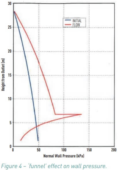
The original 1960s design allowed for only static loading to the structures and failed to account for the ‘funnel’ effect during the emptying of the silos with insufficient hoop reinforcement in place to deal with such live loads. The most common design errors were bending of circular walls caused by eccentric withdrawal, large nonsymmetric pressure caused from inserts, ignoring flow patterns and materials properties concerning temperature and moisture, corrosion of steel reinforcing bars in the concrete and improper reinforcement.
Forty years later their condition had declined to an extreme state rendering them in need of extensive structural strengthening and specialist concrete repair works which included ultra-high pressure hydro demolition and dry process gunite reinstatement.
Leading on from these investigations and designs, Freyssinet were engaged to carry out initial prototype repairs and strengthening to an initial three silos in order to verify and refine work methods and scope for the remainder of the structure. These works were undertaken from a series of special purpose mast climbers which provided for access platforms contoured to the silo geometry. Repairs were undertaken using techniques commonly used throughout the Freyssinet group internationally, including a combination of hydro-demolition and dry process shotcrete. Staging of the repairs was originally not anticipated, but was found to be necessary given the very large scale of these works, with this structural assessment undertaken internally by Freyssinet.
Structural strengthening was undertaken using proprietary Freyssinet external post tensioning including 1R15 anchorages, with successful completion of these initial works confirming the design assumptions. The prototype was completed over a twelve-month period. Based on the extensive learning and verification made possible during this initial prototype, along with the inclusion of certain methods preferred by the client, the scope of ongoing work was refined and re-valued.
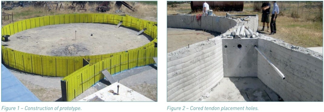
In order to verify the Freyssinet techniques for repair and strengthening initial works included the construction of a prototype off site to confirm the accuracy of coring of the interconnecting diaphragm between silos as shown in Figure 1.
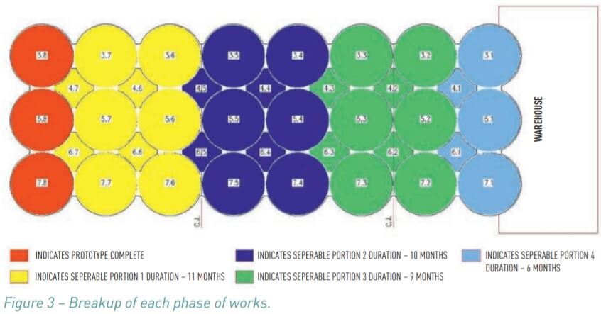
Coring of primary 90 mm diameter holes through the 4500 mm long diaphragms was completed with secondary core holes drilled to intercept these, allowing tendons to pass around the full circumference of each circular cell as shown in Figure 2.
Works on site commenced in 2008 on the first three silos as part of the initial 18-month ‘proto-type’ phase. This phase was then followed by the ‘full scale works’ whereby the overall works package was split into four distinct separable portions (SP1 – SP4) with each addressed as sequential independent schemes as illustrated in Figure 3.
Understanding the Concrete Problem
Initial site inspections gave a clear indication of the level of cracking on the silos. Extensive areas were visible where corrosion was evident due to delamination of the concrete and pimples/lateral deformations on some silo walls, as a result of the ‘funnel effect’ (Figure 4) during the operational use of the silos.
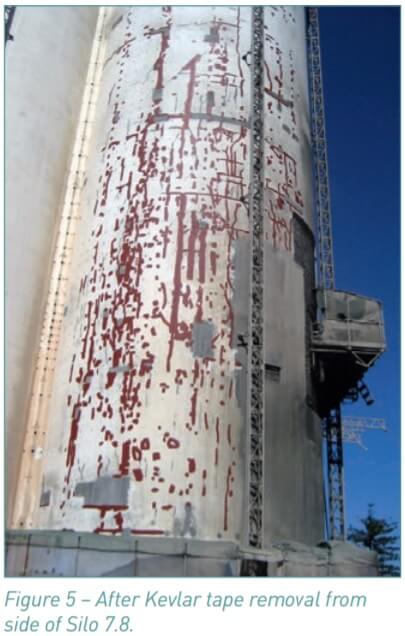
Some remediation works had been carried out previously on the cracking with Kevlar tape placed over each crack to try and stem the cracking and also seal the cracks from the elements. The extent of the cracking exposed can be clearly seen in Figure 5 following removal of the tape as part of the initial repair process.
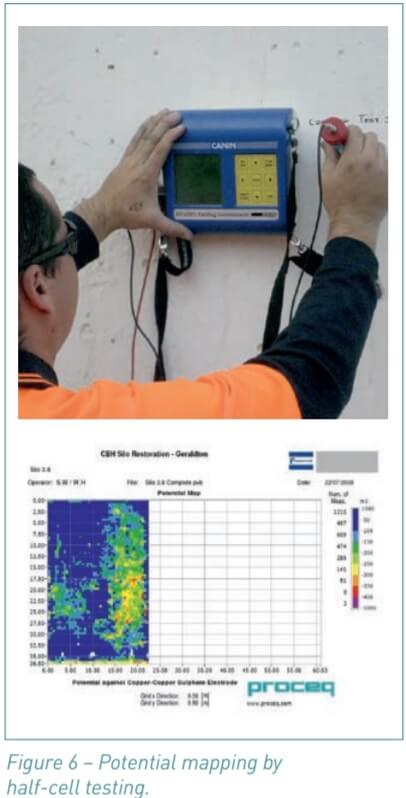
A corrosion survey was undertaken by potential mapping using half-cell testing equipment as shown in Figure 6.
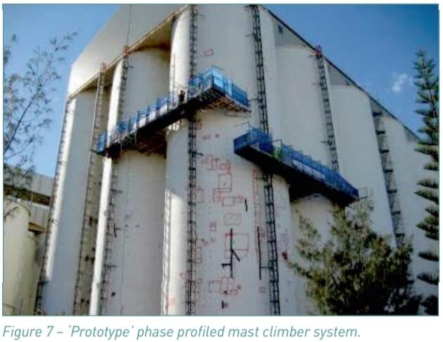
After detailed hammer surveys, coupled with exploratory breakout ‘windows’, areas of concern were identified, catalogued and each silo mapped accordingly which allowed for a repair scheme to be formulated in what became known as the ‘prototype’ phase of the works. The ‘prototype’ phase of the works utilized separate twin profiled mast climber systems for access to carry out the surveys and the repair works as shown in Figure 7.
Internal 3D scanning of the worst affected silo (3.1) was carried out noting the ‘full thickness’ cracking that was affecting this particular silo wall. These cracks coincided with areas of the wall that appeared to be ‘bulging’ outwards. The 3D scanning mapped the extent of the internal cracking and also the profile of the lateral deformation in the wall. For this case a methodology for a full depth repair was required and developed.
These initial trials led to development of a structural repair and strengthening solution comprising of the Freyssinet 1X15 external post tensioning system being utilized as the structural strengthening component to combat the insufficient hoop reinforcement, together with varying different concrete repairs techniques to combat the extensive cracking, delaminated concrete and lateral deformation affecting one of the silo structures. Due to the facilities proximity to the coast the cracking also contributed to widespread chloride induced corrosion of the existing reinforcement embedded within the structure.
Repair Solutions
After the ‘prototype’ phase, Freyssinet Australia was engaged on a full design and construct contract to remediate the remaining 21 interconnected silos and the 14 star cells. Execution of the rehabilitation solution involving various different concrete repair techniques and structural strengthening, discussed in detail hereafter, which ensured the ongoing operational efficiency and durability of the concrete storage facility.
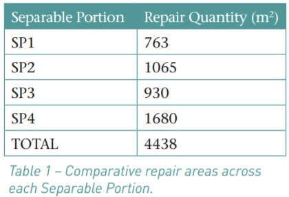
The original contract estimate for repair area was set at 3000 m2. However over the course of the project with better access to carry out detailed surveys the final repair area grew to over 4400 m2. The Table 1 below illustrates the comparative spread of repair area across each of the Separable portions.
Out of the ‘prototype’ phase of the works a defined project scope of works and access requirements were developed for each silo’s remediation.
Access Systems
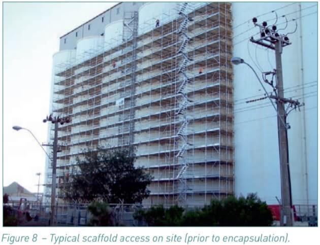
During the ‘prototype’ phase of the works profiled mast climbers (Figure 7) were utilized to access the repair areas. However it quickly became apparent that this access system was not the best solution for a project of this magnitude. With such large areas of repair to be completed, the mast climber system didn’t allow for the autonomy required to work on multiple work fronts at any given time. Also because of the lower safe working load (S.W.L) of the mast climbers a traditional scaffold access system (Figure 8) was utilized for SP1 – SP4.
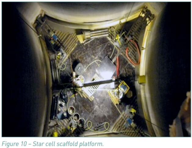
Another unique challenge was the access system for the internal star cells. Access into these areas was a difficult challenge due to the confined space nature of the works. Access doors at the base of each cell allowed for scaffold material to be passed into each cell and a scaffold ‘donut’ platform (Figure 9) to be constructed to suit the cells configuration. Side guides/rollers and a winch system were used to traverse the ‘donut’ up and down the star cell walls. Emergency access was by means of rope access system in/out of the escape hatch at the top of each cell created by removal of each silos grain feed chutes.
Outline Scope of Works
The following repair sequence was utilized across all silos:
- Conduct a Hammer Survey to identify areas of defective/delaminated concrete.
- Remove defective/delaminated concrete using a combination of both hydro-demolition and hand breakout techniques, and trim original concrete to give access behind (by a ‘gloved hand’/ ≥ 25 mm) the existing reinforcement.
- Remove existing horizontal reinforcement and replace with new galvanized steel.
- Blast and treat the existing vertical steel with a zinc-rich epoxy primer (Nitoprime Zincrich) to protect the steel reinforcement within the repair areas.
- Apply concrete repairs to areas requiring reinstatement using a high strength (45 MPa), high strength, low shrinkage dry-spray gunite (Guncrete E) repair application (>600m3 ).
- Carry out crack repairs to any remaining structural cracks.
- Apply a 3-coat high performance water based protective façade coating system to the silo external surfaces (EmerClad).
- Install an external post tensioning system using diaphragm cored holes to pass each cables external ducting which house the greased and sheathed 15.7 mm strand through and around each silo at a pre-determined location (> 26 km strand). Stainless steel pins were used to support the tendons.
- Reinstate all infrastructure for each silo – fumigation pipes, chutes, access towers etc.
In addition to the silos, the internal ‘Star Cells’ which made up the voids between the interconnecting silos and were also used for grain storage, required some works as part of the overall remediation project. The following repair sequence was utilized across all star cells:
- Install stressing anchor to receive the external post tensioning cable.
- Following completion of the post tensioning works, anchor steel mesh to the face of each Star Cell wall.
- Apply 80 mm thick strengthening skin of wet-spray shotcrete (Guncrete E) onto steel mesh and finish smooth.
- Reinstate all infrastructure for each cell – fumigation pipes, chutes etc.
Silo 3.1 required special attention in the overall repair scheme due to the lateral deformation in its mid-section as identified by the 3D mapping and also from the visible penetration through the silo wall. Once access was established, a full depth repair to an area approximately 30 m2 was required. Briefed with the 3D mapping information and as-built drawings, a structural finite element analysis (FEA) was carried out to ascertain the structural integrity of the Silo 3.1 and the extent of the necessary repairs
The results of the FEA confirmed that the silo could still function even with the lateral deformation/‘bulge’ left in place. This FEA analysis outcome allowed for the minimum possible area of full depth concrete repair to be addressed.
The results of the accompanying site investigations also highlighted the need for the extensive cracking around the full depth repair area to be treated so that the substrate would act in a homogenous manner during the stressing works, along with the need for stainless steel dowel pins to be installed to the segmented ‘blocks’ of concrete which had been created by the cracking.
Conclusions
The concrete remediation techniques and practices adopted on the Geraldton Grain Silos project were both varied and challenging making it a unique project within the Concrete Engineering field.