For those involved in managing asset integrity in the petrochemical industry, it is possible to list more than 50 different damage mechanisms that can adversely affect the fixed equipment in our refineries. But if you examine your equipment failure history, you will be surprised to find that more than 60 percent of process pipeline failures are mainly due to only three corrosion mechanisms:
- Corrosion under insulation (CUI)
- Corrosion under support (CUS)
- Stress corrosion cracking (SCC)
Why only these three? It is likely because these three corrosion mechanisms are inherently difficult to detect in the early stages. Even so, advancements in the corrosion field allow us to detect and control them through proper material selection, adjusting operating parameters, controlling corrosion environments, developing systematic procedures and by proper nondestructive evaluation (NDE) methods.
Then why do CUI, CUS and SCC continue to be the main villains on our pipeline failure data sheets? It is mainly because either we fail to develop our own specific plans to inspect for these damage mechanisms or we fail to implement inspections properly.
In this article, I attempt to consolidate the CUI detection methods currently available for the petrochemical industry. This will help you develop your own site-specific procedure to identify and control CUI. This procedure is an essential element in any corrosion control document for a modern petrochemical plant. (Learn about CUI prevention in Understanding Insulation Chemistry Proven to Inhibit CUI.)
The CUI Survey: Identifying CUI-prone Equipment
Before you start your CUI site inspection, the most important first step is to complete a CUI survey of your entire plant. This will help you to identify the pipeline circuits most prone to CUI and rate them based on severity. As supported by the American Petroleum Institute's API 581 guidelines, this is an essential element in the risk based inspection (RBI) process. This preliminary sorting saves a lot of time during field inspection. For this initial step you will need the following inputs:
- Pipeline metallurgy: Knowing the metallurgy of your pipelines is one of the prime deciding factors in whether your piping circuit is CUI-prone or not. Carbon steel (CS) and austenitic stainless steel (SS) are more susceptible to CUI. Carbon steel undergoes general thinning under insulation, and stress corrosion cracking (SCC) is the prime damage factor in austenitic SS experiencing CUI. Ferric steel is less prone to CUI.
- Operating temperature: API 571 gives the temperature range for CUI as -12°C to 175°C (10.4°F to 347°F) for CS, and 60°C to 205°C (140°F to 401°F) for austenitic SS. The rate of corrosion increases with an increase in temperature, with the most severe corrosion rate between 100°C and 120°C (212°F and 248°F).
- Operating temperature cycles: Variation in operating temperatures over the life history of the equipment is also an important factor. Some pipelines can become CUI-prone even though their normal operating temperature is above the CUI range. An example of this is standby equipment running in intermittent service. Precautions should be taken to ensure these items are included on your CUI-prone equipment list.
- Coating under insulation – its nature and age: Until the 1980s, the industry did not understand that the environment under insulation was almost like immersion conditions, so the correct types of coating were not always applied. As a result, much of the surface under insulation older than 15 years is not properly protected from CUI. Now it is widely accepted that protective coating under insulation is one of the most effective methods for preventing CUI.
- Identification of types of coating under insulation will give some idea of CUI happening on a metal surface.
- Proper coating documentation is essential for effective CUI inspection planning and maintenance in the long term.
Here are some sample notations from a CUI survey:
- Average life of 60% of the coatings under insulation is observed to be around 8 years.
- Aluminum foil wrap has been used to prevent SCC of stainless steel under insulation.
- Insulation having an inorganic zinc coating needs more attention than thermally sprayed aluminum coatings.
If there is no proper documentation available on coatings under insulation, you have two options. Either assume no coating, or carry out a random check by removing the insulation at selected locations. Conducting a CUI survey gives us initial screening data on all the equipment in a refinery, which is the essential prerequisite for field inspection.
Field Inspection: Detecting CUI Using Conventional Methods
Field inspection is a further important step to find the locations in a piping circuit that are most prone to CUI. Data should be collected in each of the following areas:
- Condition of insulation: If the insulation cladding is damaged, the risk for water ingress is increased, which accelerates CUI. Even though age is the primary concern, appearance of the insulation system also needs to be considered during inspection. While carrying out field inspection give special attention to the following areas:
- Damaged insulation cladding (often noted as a percent of total insulation).
- Caulking that has hardened, has separated or is missing.
- Sagging/low points in long unsupported piping runs.
- Bulges, staining of the jacketing system or missing bands.
- Systems in which vibration has a tendency to inflict damage to insulation jacketing, thus providing paths for water ingress.
- Steam traced systems experiencing tracing leaks, especially at tubing fittings beneath the insulation.
- Cold service equipment consistently operating below the atmospheric dew point.
- Inspection ports or plugs which are removed to permit thickness measurements on insulated systems.
- Operating environment: Areas having high humidity and salinity are always prone to corrosion and CUI is not spared from that. Plants situated in places with high annual rainfall or warmer, marine locations are more susceptible to CUI than plants located in cooler, drier, mid-continent locations. Similarly, equipment located near cooling towers and steam vents are highly prone to CUI. And plants whose operating temperatures cycle through the dew point on a regular basis are also susceptible. API 581 lists the following locations as highly susceptible for CUI:
- Areas exposed to mist overspray from cooling towers.
- Areas exposed to steam vents.
- Areas exposed to deluge systems.
- Areas subject to process spills, ingress of moisture or acid vapors.
- Geometry of pipeline and other design considerations: Locations where water will naturally collect before evaporating are more susceptible. Similarly dead legs, pipe hangers and other supports are susceptible areas. Give priority to inspecting the following locations under insulation in a piping circuit:
- Protrusions through the insulation such as vents, drains and steam tracer tubing.
- Irregular insulation surfaces (valves and fittings).
- Termination of insulation at flanges and other piping components. (Learn more about Flange Corrosion Repair and Protection.)
- Termination of insulation in a vertical pipe.
- Low points in piping systems that have a known breach in the insulation system, including low points in long unsupported piping runs.
- Carbon or low-alloy steel flanges, bolting and other components in high-alloy piping systems.
- The first few feet of a horizontal pipe run adjacent to the bottom of a vertical run.
- Pipe supports and pipe hangers.
- Inspection windows: To enable random inspection of insulated pipelines, small pockets can be cut in the insulation, which can be removed and fitted back without damage. Both visual and thickness measurement is carried out at regular intervals in these locations. The real challenge is identifying the locations for inspection windows to provide an accurate representation of the entire circuit.
- There are some disadvantages to this technique, such as difficulty in cutting enough windows to get a reliable result.
- In addition, inspection windows may compromise the integrity of the insulation and promote CUI if covers are not reattached carefully after inspections.
Data from field inspection gives an idea about the severity of CUI in piping circuit. This is the deciding factor that determines the effectiveness of inspection. Figure 1 can be used as a guide for selection of an inspection plan.
Figure 1: Extent of CUI inspection based on field observations
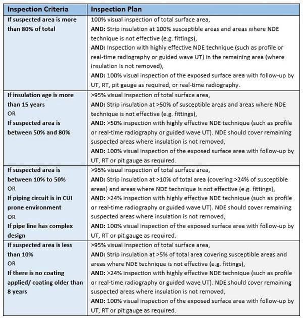
PLEASE NOTE: Guidelines given in Section 1 above can be used to calculate the percent of area where CUI is suspected. Guidelines given in Section 2 above can be used to identify environments prone to CUI. Guidelines given in Section 3 above can be used to decide the complexity in design that affects CUI.
Figures 2-3: Inspection windows cut into the jacketing and insulation of a storage tank


We can effectively detect CUI in its early stages using these conventional methods of systematic planning, documentation and inspection. (Other methods to detect CUI are nondestructive testing and imaging methods, which can be highly effective for inspecting hard-to-access pipelines, discussed in Nondestructive CUI Detection Techniques for Process Pipelines.)