Stress corrosion cracking (SCC) is the cracking caused by the combined influence of tensile stress and a corrosive environment. In the worst case it can lead to sudden failure of normally ductile metal alloys, especially at an elevated temperature. (For in introduction to this topic, read the article What Causes Stress Corrosion Cracking In Pipelines?)
An Incident of Stress Corrosion Cracking (SCC) in a Pipe
In a July 2011 incident, a leak was reported from a 2” diameter pipe to a pressure safety valve in a compressor plant. Two additional leaks in similar lines were also reported over the subsequent two-day period. The red line in Figure 1 shows the location of the leaks in two flare pipes located upstream of the pressure safety valve on adjacent compressor trains.
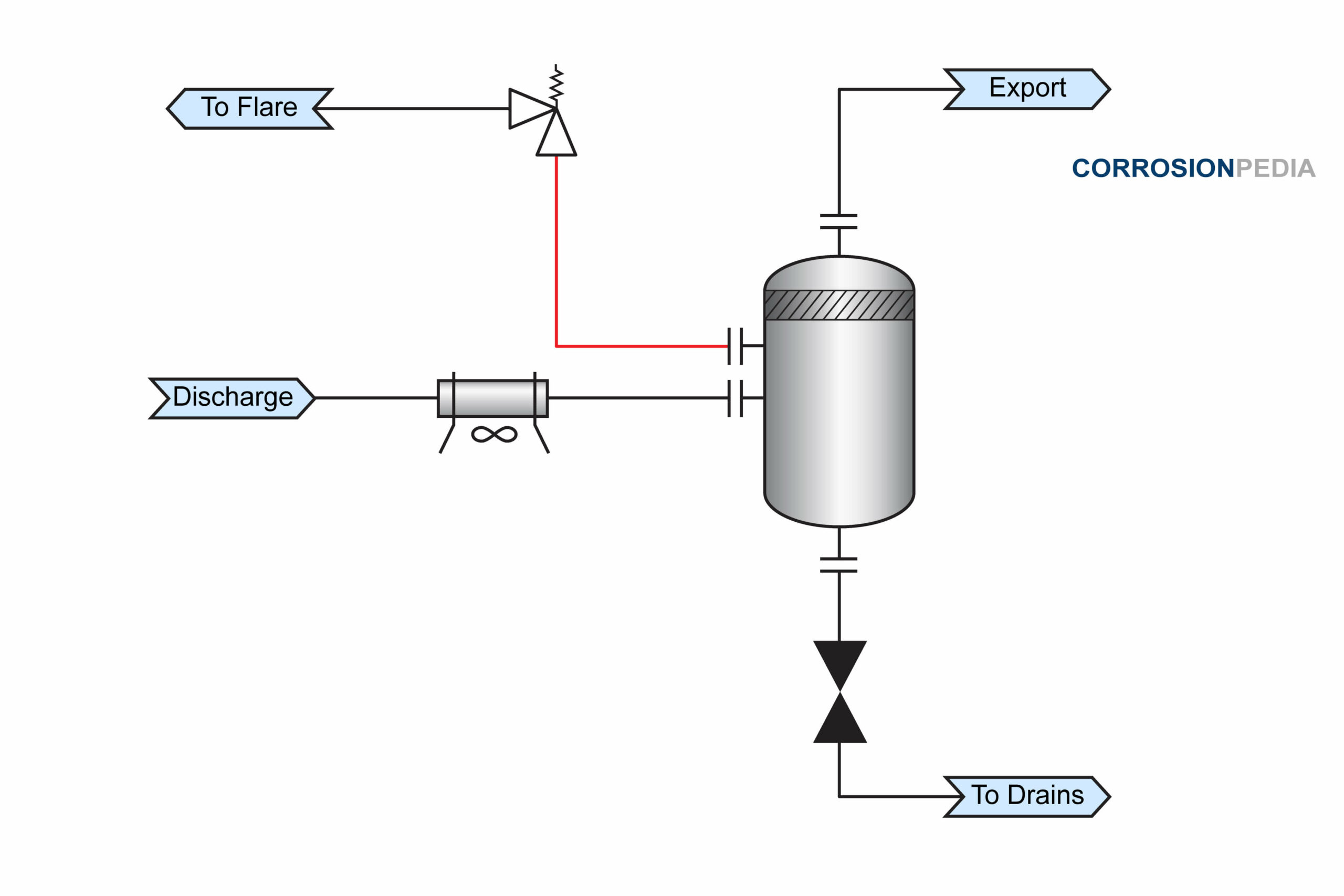 Figure 1. Process schematic showing failure location.
Each failure was located at a pipe to elbow weld in a horizontal section. The leak was in the top pipe section and within the heat affected zone (HAZ) of the weld. All the failed sections were then removed for further investigation.
Investigation of the Stress Corrosion Cracking Incident
Black deposits were found in the lower half of the pipe, which indicated that a liquid had been accumulating at this location. Microscopic examination also revealed the presence of cracking on the pipe's outside surface, including a 13 mm hairline crack. After cleaning with nitric acid to remove corrosion products, the cracks became visible to the naked eye.
Macrophotographs showed that pitting and cracking occurred primarily in the weld and the parent material. Stress corrosion cracking has a distinct morphological feature of intergranular cracking with some branching (Figure 2).
 Figure 2. Microphotograph of stress corrosion cracking showing branching.
Source: NASA Corrosion Engineering Laboratory.
The Root Cause of the Failure
The concentration of hydrogen sulfide (H2S) in the flash gas from the compressor discharge was about 11 mol.-% (5.5 bar partial pressure). It was also saturated with water with a chloride content of 260 – 900 ppm. The normal operating temperature is 52°C (126°F), which is just below the ISO 15156 limit for austenitic stainless steel in the presence of chloride. Hot summer ambient temperatures and fouling of the tube fins also exacerbated the already harsh environment. The standard maintenance procedure was to switch off the cooler, wash the fins with water, and switch the cooler back on with the improved cooling capability. However, during the procedure a high temperature occurs temporarily when the cooler is switched off.
Understanding NACE MR0175 and ISO 15156
NACE MR0175 and ISO 15156 are the standards for materials for use in H2S-containing environments in oil and gas production, and were issued as a recommendation of threshold limits of H2S above which precautions against environmental cracking are considered necessary. In its first publication in 2003, the limit of AISI 316L stainless steel is 60°C (140°F) maximum when chlorides exceed 50 ppm.
After conducting laboratory testing, researchers argued that the limitation for austenitic stainless steels can be expanded to a more severe environment than the original ISO 15156 restrictions. In 2007, the restrictions for AISI 316 materials were updated and officially endorsed in the 2009 version of the standard.
The failures reported in the industry occurred in an environment that is considered susceptible under the current ISO 15156 restrictions, but would be classified as non-susceptible under further recently proposed relaxations. The majority of the reported failures occurred just after 4 months and up to 3.5 years of service in different facilities.
Several reported failures are shown and marked on Figure 3. The three colored zones represent the limitation imposed by ISO 15156 in its original form (color 1), as modified in both 2007 and 2009 (color 2), and the further relaxations recently proposed (color 3). Note that a number of failures occurred in the yellow zone, which is permissible based on laboratory testing. This indicates that there is a disparity between laboratory testing and industry experience.
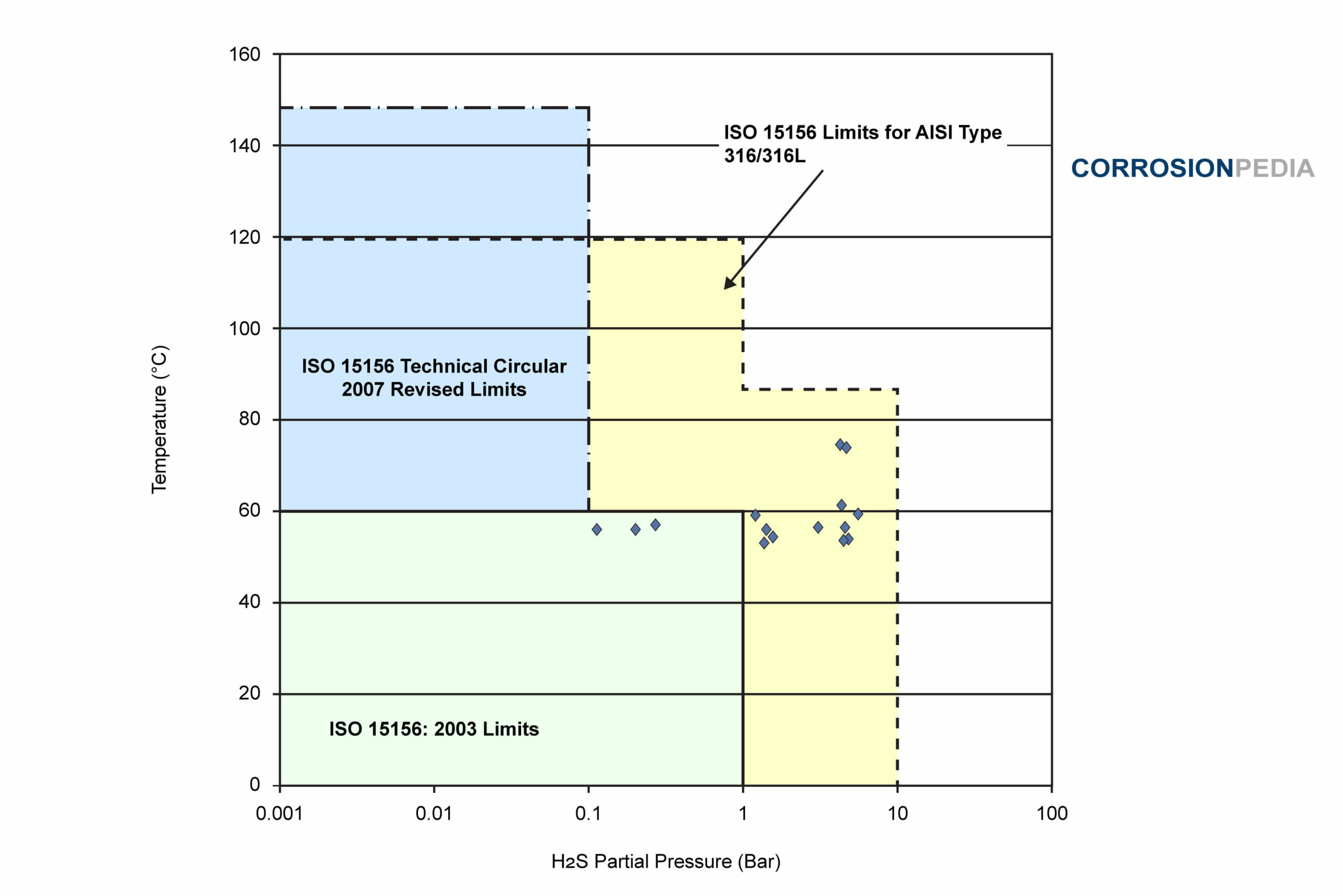 Figure X. Plot of industrial failures for AISI 316/316L for a maximum chloride content of 1000 mg/L.
The first possible explanation for the disparity is that laboratory testing is performed in a liquid environment whereas the reported failures occurred in vapor phase. Wet vapors are prone to chloride accumulation due to the effects of evaporation and condensation. Solids removed from the inside surface of the failed component in the aforementioned incident contained a high concentration of chlorides exceeding the liquid's concentration.
A second factor can be a residual stress that varies from weld to weld. Test results can vary substantially for welded test specimens depending on the welding parameters. (Related reading: Causes and Prevention of Corrosion on Welded Joints.)
Thirdly, stress corrosion cracking of austenitic materials requires a significant incubation period. The test exposure time can be a significant factor and difficult to replicate in an accelerated test typically conducted in the laboratory.
Finally, the surface condition of the weldment, including the presence of heat tint and a heat affected zone, can have an influence on the metal's corrosion resistance. Heat tint consists of various oxides depending on the parent metal and the thermal history of the weldment. Different oxide forms have different corrosion resistance values.
Prevention of Stress Corrosion Cracking
Residual stresses generated during welding can be relieved by stress-relief annealing, and the same is commonly used for carbon steels. However, for austenitic stainless steels, the threshold value for residual stress is very low in chloride environments. As a result, the annealing or post weld heat treatment is less effective for austenitic stainless steels in chloride-containing environments.
Mechanical work or treatment could be done to introduce residual compressive stresses to counteract the tensile stresses generated during welding. Treatments like shot peening or grit blasting result in surface compressive stress and are beneficial for controlling SCC.
The Influence of Alloy Composition on Stress Corrosion Cracking
Resistance to chloride SCC depends on the type of stainless steel being used. The austenitic grades of stainless steel are more prone to SCC, and their resistance to SCC depends on their nickel content.
Austenitic grades with nickel contents in the range of 8 to 10 wt% (e.g., 304/304L and 316/316L) are more prone to such attack due to SCC. Austenitic grades that have high nickel and molybdenum contents such as alloy 20, 904L and the 6% molybdenum super austenitic grades are superior with respect to SCC.
The ferritic grades of stainless steel, such as type 430 and 444, are also very resistant to chloride SCC.
In addition to laboratory testing, real-world industrial experience is also an important factor in determining standards, code restriction requirements, and approving the materials to be used in specific environmental conditions. The important points that must be taken into account are the differences that exist between vapor and liquid environments, the role of residual stress, the test duration, and the weld surface condition. With these considerations, ISO 15156 can improve industry safety by avoiding similar incidents as outlined in this article.