In the petroleum industry, pipelines are generally regarded as the most economic and efficient means of transporting hydrocarbons. Pipelines are expected to perform in temperate to tropical climates and in varying terrains, from the benign to such frontier environments as the Arctic and deep offshore. In addition, pipelines allow the safe transport of hydrocarbons through developed areas with minimal obstruction to normal human activities.
Cost and logistics are important considerations when constructing and operating the pipelines. It is paramount that the installation and operational costs of any pipeline is profitably offset by the value realized from the fluids transported. Safety and environmental protection are therefore of prime consideration as compensations, penalties and loss of use due to poor pipeline engineering and operation may be many times more than the economic value of the products. Therefore, it is important to maintain pipeline integrity, and this is usually achieved by reducing the rate of corrosion.
Impurities Commonly Found in Natural Gas
Taking natural gas pipelines into consideration, impurities in the natural gas play a key role towards accelerating corrosion, thereby decreasing the service life of the pipeline while increasing the maintenance costs. Additionally, pipeline leaks due to corrosion can lead to contamination of the soil, threaten human and aquatic life and have adverse environmental implications.
The common impurities present in natural gas are hydrogen sulfide (H2S), oxygen (O2), carbon dioxide (CO2), water (H2O) and in some cases mercury (Hg). (Discover the other corrosion causing impurities in The 6 Corrosive Components That Can Be Found in Crude Oil.) The combination of H2S and CO2 are popularly known as acid gases. Oxygen can also be present in the gas stream through leaks in compressors and surface equipment.
Natural Gas Processing
Figure 1 depicts a typical natural gas processing chain that is subject to corrosion due to gas impurities. Produced natural gas usually contains certain amounts of free water and condensate, and they are removed by a surface separator. However, in certain cases the natural gas is produced dry, meaning it does not contain sufficient amounts of condensate and free water but still contains varying amounts of H2S and CO2.
Figure 1. Flow diagram of a typical natural gas processing chain.
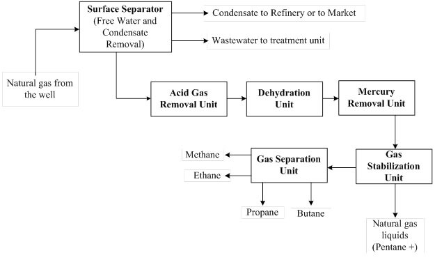
As shown in the natural gas processing chain (Figure 1), an acid gas removal unit is used to capture the CO2 and H2S in the gas stream, and this can be achieved by absorption, adsorption, membrane or cryogenic technologies. In cases where aqueous chemical solvents (absorption) are used, the dehydration unit is sited downstream of the acid gas removal unit. This is because the acid gas removal using an aqueous amine solution will saturate the treated gas (sweet gas) with water. Therefore, a downstream dehydration unit removes the H2O to the desired specification.
Taking into account future possibilities of having mercury in the gas stream, a mercury removal unit is installed downstream of the dehydration unit. The H2S, CO2, H2O and Hg free gas stream is sent to the gas stabilization unit to remove natural gas liquids (pentane plus, C5 +). The gas stream containing methane (C1) to butane (C4) is routed to the gas separation unit where demethanizer, deethanizer, depropanizer and debutanizer separation columns are used to recover the individual gas components.
The varying concentrations of CO2, H2S, H2O and Hg will cause corrosion issues along the many gas pipelines from the gas production wells to the gas separation units. Apart from corrosion problems, human and environmental concerns can be threatened by these impurities. Therefore, it is imperative that measures are taken to remove these impurities to the industry limits. Acceptable limits for H2S for all applications is a maximum of 4 ppm, while for H2O the maximum is 7 lb/MMSCF. The acceptable limit for CO2 for pipeline gas sales is a maximum of 2%, while for gas liquefaction the maximum is 50 ppm (0.005 %).
The presence of water, acid gases and oxygen in pipeline gas are common causes of corrosion. (For more on this subject, read Important Corrosion Sources in Natural Gas Dehydration Process Plants.)
Water (H2O)
If free water in the gas stream is not removed, it will lead to hydrate formation along the pipeline conveying the gas to downstream processing plants. Erosion corrosion can occur (especially at high gas velocities) due to the formation of gas hydrates, which are crystalline compounds (i.e., solids) that form when the molecular cavities of free water trap hydrocarbons. Hydrate formations are often detected when pressure drops occur along the gas pipeline. In order to avoid or reduce gas hydrate formation, chemical inhibitors (methanol, ethylene glycol, etc.) are injected at the desired dose into the gas lines.
Acid Gases (CO2 and H2S)
The formation of carbonic acid (H2CO3) due to the presence of free water and CO2 is another source of aggressive corrosion in gas pipelines. The removal of CO2 or free water will interfere with the reaction route; therefore surface separators should be operated efficiently to avoid carry over of free water with the gas stream. On the other hand, during pipeline transportation of gas, free water can also be formed in the low gas velocity and stagnant regions, hence the possibility of H2CO3 formation. Corrosion due to H2CO3 is of tremendous concern to companies that produce natural gas with very high CO2 concentration, especially in the production of unconventional natural gas or in cases where CO2 is injected for enhanced gas recovery. This is because CO2 is not easily removed from the flowing gas stream until it enters the acid gas removal unit, and in some cases the gas pipeline can be several kilometers long.
Hydrogen sulfide (H2S) also coexists with CO2 in many gas streams, and its presence causes severe corrosion on the internal surface of pipelines. The iron (iron ions) content of the metal is attacked by H2S (sulfide ions) to form an iron sulfide film according Eq. (1). Although the iron sulfide serves as a bridge between the H2S in the gas stream and the surface of the metal, high gas velocities can sweep away this iron sulfide, hence additional corrosion occurs. Similar scenarios occur for CO2, H2O and metal reactions that forms iron(II) carbonate (FeCO3), as shown in Eq. (2).
Eq. 1: Fe2+ + S2- → FeS(s)
Eq. 2: Fe2+ + CO32- → FeCO3(s)
Apart from corrosion, the lethal effect of H2S is the major reason why gas leaks will not be tolerated. There are cases where an H2S scavenger (e.g. triazine) is injected into the gas pipelines to convert H2S to the less corrosive dithiazine (insoluble solid).
Oxygen (O2)
The O2 content in a natural gas stream can be both from the initial O2 content from the gas production well and from O2 ingress from leaking process equipment (compressors, valves, flanges, etc.). As a strong oxidant, O2 reacts quickly with iron to form iron(III) oxide as shown in Eq. (3). In the presence of moisture, corrosion due to O2 and CO2 is accelerated because of the dissolution of O2 in H2O leading to the formation of iron(II) hydroxide, iron(III) hydroxide and iron(II) carbonate (Eqs. (4) to (6)). These iron films have the tendency to wash away during high gas velocities, thereby promoting further corrosion.
Eq. 3: 2Fe(s) + 1.5O2(g) → Fe2O3(s)
Eq. 4: 2Fe(s) + O2(g) + 2H2O(l) → 2Fe(OH)2(s)
Eq. 5: 2Fe(OH)2(s) + 0.5O2(g) + H2O(l) → 2Fe(OH)3(s)
Eq. 6: Fe + CO2 + 0.5O2 → FeCO3(s)
Other factors that can accelerate CO2, H2S and O2 related corrosion is the CO2, H2S and O2 partial pressures, gas stream temperature, etc.
Oxygen related corrosion can be mitigated by using gas blanketing when injecting methanol (hydrate control) and H2S scavengers into gas pipelines, and by avoiding mechanical damage to the equipment (downhole to surface equipment).
Pipeline Coatings as a Corrosion Barrier
Another approach of minimizing corrosion is to create a barrier between the metal surface and corrosive media.
The corrosive media can be in the gas stream (internal pipeline corrosion) or from the surrounding environment (external pipeline corrosion). Coating a gas pipeline is also very important because H2S and CO2 in the gas stream is difficult to remove before entering the acid gas removal unit. Therefore, the pipelines conveying the gas from the production site to the acid gas removal unit are susceptible to corrosion. This is where coating a gas pipeline become integral towards corrosion mitigation and control. When corrosion on the internal surface of the pipeline is severe, the external coating protects the pipeline from leaks that can lead to blowouts, aquatic and human health issues and environmental problems.
There are various types of pipeline coatings, and their selection depends on weather conditions, soil conditions, gas composition, gas temperature and pressure, and pipeline location (aboveground, underground or sea bed).
Coal Tar Enamel
Coal tar enamel is usually used to coat the external surfaces of gas pipelines.
Merits:
- Mostly applied to buried (underground) pipelines and pipelines on the sea bed (subsea pipelines).
- Low installation and maintenance cost.
- Can withstand high operating temperatures.
- High resistance to hydrocarbons, water, bacteria and chemicals in the soil.
Demerits:
- Emission of carcinogenic vapors that are potential health and environmental hazards, and a threat to aquatic life. Reinforcements are applied on top of coal tar to avoid the associated emissions.
- Not used for pipeline internal surface coating due to possible contamination of the gas stream (poor chemical resistance).
- No longer a popular coating option.
Fusion Bonded Epoxy (FBE)
Another option is a fusion bonded epoxy (FBE).
Merits:
- Very good resistance to moisture, oxygen, chlorides etc. (i.e., chemical resistance).
- Also serves as an insulating material due to low conductivity.
- Excellent adhesion on metallic surfaces.
- Can be applied both on the internal and external surfaces of gas pipelines.
Demerits:
- Higher installation cost due to the necessary heating for the pipe and coating.
- Material is expensive.
- Fragile.
Polyolefin Coatings
The two main types of polyolefin coatings are single polypropylene (PP) and polyethylene (PE) coatings.
Merits:
- PP has higher mechanical strength than PE.
- PP has high resistant to organic solvents.
- PP can be used for internal coating.
- Low price.
Demerits:
- Lower adhesion on stainless steel pipes.
- Has low thermal resistance.
- PE has low resistance to O2 and CO2.
- PE has low resistance to strong oxidants like O2.
Polyurethane (PUR)
Polyurethane is an extremely versatile coating.
Merits:
- Chemical resistance is excellent.
- High adhesion.
- Can withstand high operating temperatures and pressures.
- Fast curing time even at low ambient temperature.
- Can be used for both internal and external pipeline coatings.
Demerits:
- Material cost is high.
- Sensitive to moisture.
- Can produce toxic products when decomposed.
Multilayer Coatings
Multilayer coatings apply more than one coating to provide more protection for the pipeline. This can be in the form of double layer–FBE, three layer polyethylene (3LPE) tape and three layer polypropylene (3LPP). In 3LPP and 3LPE, the initial coating is an FBE followed by a layer of adhesive, then the polypropylene or polyethylene outer layer is applied. The lower adhesion of PE and PP is the reason behind the use of 3LPE and 3LPP.
Merits:
- Low material and installation cost.
- Outstanding mechanical resistance (3LPE and 3LPP).
- Very low permeation of water.
- High adhesion properties.
- 3LPE and 3LPP has high bending characteristics during pipeline laying operations.
- Double layer–FBE can operate up to 110ºC (230ºF).
- Double layer–FBE has tough physical properties that are beneficial during pipeline transportation.
- 3LPE can withstand temperatures between 40ºC to 85ºC (104ºF to 185ºF).
- 3LPP can operate at low temperatures of –40ºC) up to 140ºC (-40ºF up to 284ºF).
- Good combination of properties.
Demerits:
- 3LPP and 3LPE offer limited resistance to oxidants such as oxygen, amines and sulfur.
- Double layer–FBE has poor flexibility if the thickness is high.
Conclusion
Technology is continually evolving, and such a trend is observed in pipeline engineering. The need to develop oil and gas infrastructure in increasingly difficult terrain implies that state-of-the art equipment and methods must be employed in pipeline design, construction and operation. The application of simulation in pipeline design and the use of remote monitoring of pipeline systems (see Remote Corrosion Monitoring Systems in the Oil and Gas Industry for more information) during operation are examples of high-tech deployment in pipeline engineering. In addition, the shift to deeper waters for hydrocarbon exploration and production implies that conventional pipeline engineering methods should be revised to safely install and construct pipelines in these harsh environments.
During gas pipeline operation, operators should maintain optimal gas velocities to avoid stagnant region and flaking of iron films. This is where gas pipeline monitoring becomes very important.
Adequate removal of free water using surface separators, injecting hydrate inhibitors and H2S scavengers all work together to minimize the corrosion chemistry.
Internal and external pipeline coatings also play key roles to prevent the pipeline from coming into contact with the corrosive media. The service life of the pipeline is extended as a result.
All these corrosion mitigation strategies are put in place to reduce the downtime, expense, and environmental and health problems associated with pipeline corrosion.