Measuring the corrosion rate (the velocity at which metal is lost) of equipment or a metallic structure such as a bridge, pipeline, tank or pressure vessel is a valuable piece of information for estimating the structure’s condition and its remaining service life. Armed with this information, timely actions can be taken before the structure fails. (Learn more about the causes of corrosion in these types of structures in The Key Causes of System-Dependent Corrosion in Piping Systems.)
Depending on the inspection method used to measure it, the corrosion rate (CR) can be expressed in many ways, including:
However, the wall thickness loss is the most widely accepted form due to its usefulness in predicting the equipment’s remaining life. Knowing how to interpret and convert between these various reporting formats of the corrosion rate is necessary to properly analyze and compare information from different sources.
This article will explain how the corrosion rate is obtained from different inspection methods and how to convert units among these various formats. It is important to ensure unit consistency when calculating the corrosion rate and converting among the different formats of the parameters involved in the equations.
Corrosion Rate Expressed as a Penetration Depth (Wall Thickness Loss)
The velocity at which the metal loss progresses into a structure’s wall can be determined by measuring the metal loss depth using pit gauges (Figure 1) or laser scanners, or by measuring the remaining wall thickness (Figure 2) and subtracting this amount from the original or local unaffected wall thickness. (Laser scanning is examined in the article The Use of Laser Scanning when Conducting Fitness-for-Service Corrosion Assessments.)
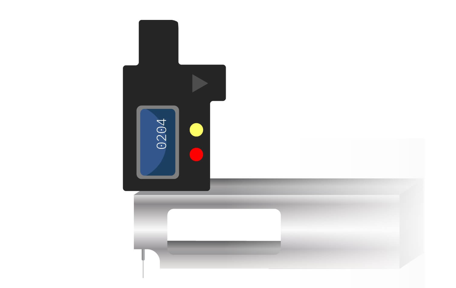
Figure 1. Depth measurement using a pit gauge.
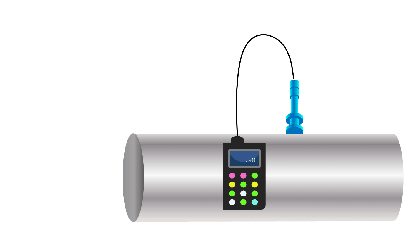
Figure 2. Remaining wall thickness measurement.
In this case, the corrosion rate is obtained by dividing the change in the depth of the metal loss into the time interval between the inspections. The corrosion rate’s unit of measure will be distance per time, i.e., speed, such as millimeters per year (mm/y) or mils penetration per year (mpy).
|
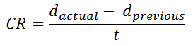
Calculating corrosion rate (CR) using depth of metal loss
|
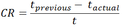
Calculating corrosion rate (CR) using remaining wall thickness
|
 ![]() |
 |
|
CR = corrosion rate in units of distance per time (i.e., speed)
|
|
dactual = metal loss depth in latest inspection
|
tprevious = remaining thickness in previous inspection
|
|
dprevious = metal loss depth in previous inspection
|
t actual = remaining thickness in latest inspection
|
|
t = time between dprevious and dactual
|
t = time between tprevious and tactual
|
Table 1. Calculating the corrosion rate (CR) using the depth of metal loss or remaining wall thickness.
Corrosion Rate Expressed as a Mass Loss
Obtaining the corrosion rate from mass loss implies the use of gravimetric coupons that are exposed to the operational environment that we want to assess (e.g., a process fluid or external environment). This is an indirect method for assessing the corrosion rate because the measured mass loss is from the coupon and not from the structure itself.
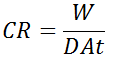
In this case, the corrosion rate is obtained by dividing the change in the mass of the coupon (mass loss) by the time the coupon was exposed, so the units of the corrosion rate will be mass per time, or mass flow (e.g., g/y). Converting from a mass loss rate to a wall thickness loss is performed by making use of the density of the exposed material and assuming a given corroded area (e.g., X% of the exposed surface).
In cases where the coupon shows pitting corrosion, the pitting corrosion rate can be measured as per the method explained in the previous section (penetration depth) but using optical microscopy as a measuring tool. (Learn more about pitting corrosion in Pitting Corrosion in Oil and Gas Wells and Pipelines.)
|
Calculating the corrosion rate (CR) from mass loss
|
 |
|
CR = corrosion rate in units of distance per time (i.e., speed)
|
|
W = mass loss
|
|
D = density of coupon metal
|
|
A = corroded area (X% x initial exposed area) of the coupon
|
|
t = exposure time of the coupon
|
Table 2. Calculating the corrosion rate (CR) from the mass loss.
Corrosion Rate Expressed as a Current Flow
The corrosion process implies an occurrence of electrochemical reactions and its consequent transfer of electrons between the corroding material and the surrounding environment; therefore the flow of corrosion current is another way to express the corrosion rate. This principle is used by linear polarization resistance (LPR) probes, which are an indirect method to assess an environment’s corrosion rate because the measured corrosion current is from the probe's circuit and not from the structure itself.
Note: This can also be a direct but highly inaccurate method of assessing the corrosion rate of a system because in practical applications (e.g., cathodic protection (CP) interference across isolation joints) it assumes a corroding area and an initial and final oxidation status of the corroding material, and sometimes even the magnitude (e.g., non-static interference condition) and duration of the corrosion process.
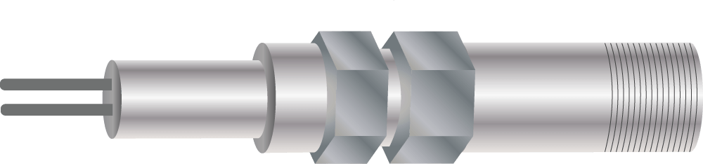
Figure 3. Drawing of a linear polarization resistance (LPR) probe.
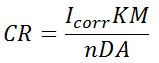
In this case, the corrosion rate is obtained either directly by measuring the current flow or indirectly by measuring the voltage difference across a known resistance, but in any case the units of the corrosion rate will be as for an electric current (A or mA). Converting from an electric current to a wall thickness loss is performed by making use of Faraday’s law, which relates the current flow to mass loss, and from there is the same as the method explained in the previous section (mass loss).
This conversion requires making an assumption about the initial and final oxidation status of the corroding material (i.e., the number of electrons lost per molecule or atom), which is not necessarily one single specie because the corrosion products from iron can be a mixture of many corrosion products with different oxidation statuses, such as FeS, Fe2O3, FeCl, etc.).
|
Calculating the corrosion rate (CR) from current flow
|
 |
|
CR = corrosion rate in units of distance per time (i.e., speed)
|
|
Icorr = corrosion current
|
|
K = constant for conversion of units [3272 mm/(A-cm-year), 128800 milli-inches/(A-cm-year)]
|
|
M = molecular weight of the corroding material
|
|
n = number of electrons lost per molecule or atom of the corroding material
|
|
D = density of the corroding material
|
|
A = corroded area
|
Table 3. Calculating the corrosion rate (CR) from current flow.
Corrosion Rate Expressed as a Change in Electrical Resistance
The flow of electrical current through a volume of any conductive material will create an electrical potential difference across the material. The magnitude of the voltage drop will be a function of the amount of current flowing, the material’s resistivity and the size of the cross sectional area. Therefore, if the area is reduced then transferring the same amount of current will create a larger potential drop across the structure.
This principle is used in corrosion monitoring tools such as electrical resistance (ER) probes, which are an indirect method to assess an environment’s corrosion rate because the reduction in the cross sectional area is from the probe’s sensing element and not from the equipment itself. However, it is also used to directly measure the reduction in the structure’s wall thickness, as in the case of field signature monitoring (FSM) and the voltage drop in a length of pipe.
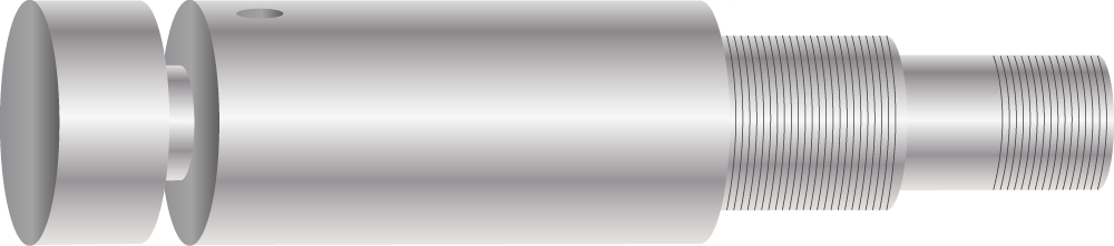
Figure 4. Drawing of an electrical resistance (ER) probe.
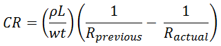
In this case the corrosion rate is obtained by dividing the change in the resistance of the circuit by the time the resistance changed, so the units of the corrosion rate will be resistance per time, (e.g., Ohm/y). Converting from the change in the electrical resistance rate to the wall thickness loss is performed by making use of the resistivity of the exposed material and the shape parameters of the corroding piece.
|
Calculating the corrosion rate (CR) from the change in electrical resistance
|
 |
|
CR = corrosion rate in units of distance per time (i.e., speed)
|
|
ρ = resistivity of the material
|
|
L = length of the piece
|
|
w = width of the cross sectional area of the piece
|
|
Ractual = circuit resistance in latest inspection
|
|
Rprevious= circuit resistance in previous inspection
|
|
t = time between Rprevious and Ractual
|
Table 4. Calculating the corrosion rate (CR) from the change in electrical resistance.